Other Parts Discussed in Thread: TINA-TI
Tool/software:
Hi,
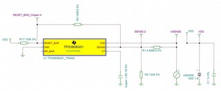
I want to simulate a design according to https://www.ti.com/lit/an/slva360/slva360.pdf in TINA-TI. I calculated the needed resistor values for a hysteresis between 9.3V and 17.1V.
But the simulation didn't work.
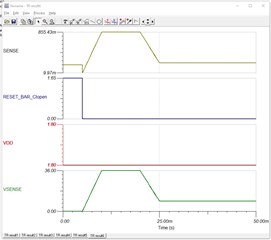
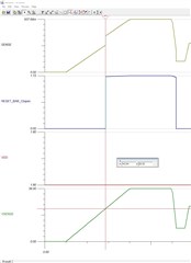
I would have expected the signal RESET_BAR_ctopen to go up at 9.3V and down at 17.1V.
Do you know where my problem is?
Thank you for your help.
BR
martin