This thread has been locked.

If you have a related question, please click the "Ask a related question" button in the top right corner. The newly created question will be automatically linked to this question.

TDA4VM: About DSI display related issues

Part Number: TDA4VM

Hi

TI Soupport team,

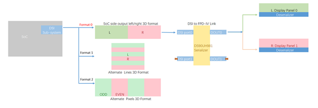
From above picture, Our custom board want to realize the ultimate goal. Got some questions need to comfirm.

I、From SoC side, Is it possible the DSI sub-system output these three modes OR one of the three Farmat ?

     1、We used PDK_80, The default output format by DSS is Left/Right format ? How to modify it to other format (in vision-app or dss driver pdk/packages/ti/src/dss/) ?

II、We used DS90UH981 serializer, Received (1280 * 2) *480 image from SoC DSI sub-system, My ultimate goal is that to use split mode inside UH981 for two display panel respectively. 

      Each display panel receive 1280 * 480. 

      1、Refer to the content of this link( https://e2e.ti.com/support/processors-group/processors/f/processors-forum/942679/faq-processor-sdk-dra8x-tda4x-how-to-change-display-resolution-in-vision-apps )

            to modify DSI output resolution (1280 * 2) * 480 to UH981. Is the modification correct ?
             

vision_apps\apps\basic_demos\app_multi_cam\app_display_module.c
        displayObj->disp_params.outWidth = 1280 * 2;//DISPLAY_WIDTH;
        displayObj->disp_params.outHeight = 480;//DISPLAY_HEIGHT;
        displayObj->disp_params.posX = (1920-DISPLAY_WIDTH)/2;
        displayObj->disp_params.posY = (1080-DISPLAY_HEIGHT)/2;
vision_apps\apps\basic_demos\app_tirtos\common\app_init.c
        prm.timings.width        = 1280 * 2U;
        prm.timings.height       = 480U;
        prm.timings.hFrontPorch  = 16U;
        prm.timings.hBackPorch   = 48U;
        prm.timings.hSyncLen     = 40U;
        prm.timings.vFrontPorch  = 5U;
        prm.timings.vBackPorch   = 3U;
        prm.timings.vSyncLen     = 5U;
        prm.timings.pixelClock   = 39400000ULL;

      2、For now, because we don not kown the Deserializer, Any possible to let me kown how to config UH981 for split mode ?

            And is there any scripts to achieve my ultimate goal ( Split  (1208 * 2)*480 to two 1280 * 480 ) , how to modify program(in vision-app or dss-driver) ?

            It would be best that you can offer a script to set up UH981 for single display panel (non-split mode). Just to verify the whether the data pathway properly under PCB !!


Best Regards

Murphy,

  • Hi Murphy,

    I、From SoC side, Is it possible the DSI sub-system output these three modes OR one of the three Farmat ?

         1、We used PDK_80, The default output format by DSS is Left/Right format ? How to modify it to other format (in vision-app or dss driver pdk/packages/ti/src/dss/) ?

    Both format1 and format2 can be supported, i could not understand format3. Fomat1 can be achieved by using two video pipelines and put video side by side in the overlay. Format2 can be achieved by extra DMA operation to keep two fields in alternate lines.. 

        1、Refer to the content of this link( https://e2e.ti.com/support/processors-group/processors/f/processors-forum/942679/faq-processor-sdk-dra8x-tda4x-how-to-change-display-resolution-in-vision-apps )

                to modify DSI output resolution (1280 * 2) * 480 to UH981. Is the modification correct ?

    The timings as such looks fine, but please check ub941 specs to make sure it is matching with the expected timing. 

    Regards,

    Brijesh

  • Hi

    Brijesh,

    thanks for your reply.

    Fomat1 can be achieved by using two video pipelines and put video side by side in the overlay.

    We want to use format 1 to realize my ultimate goal,  How to modify the code to achieve format1 (Left/Right Format 3D) ?

    please check ub941 specs to make sure it is matching with the expected timing. 

    Is there any scripts can be referred to ? like below, we want scripts on UH981 for split mode.

    //example script for UB941 for split mode 
    
    // Crop Port0 1920*720 image
    {0x1a, 0x1E, 0x01}, // Select FPD-Link Port 0
    {0x1a, 0x36, 0x00}, // Set crop start X position to 0(bit[0:7])
    {0x1a, 0x37, 0x80}, // Set crop start X position to 0(bit[8:12]) and enable cropping
    {0x1a, 0x38, 0x7F}, // Set crop stop X position to 1919 (LSB)
    {0x1a, 0x39, 0x07}, // Set crop stop X position to 1919 (MSB)
    {0x1a, 0x3A, 0x00}, // Set crop start Y position to 0 (LSB)
    {0x1a, 0x3B, 0x00}, // Set crop start Y position to 0 (MSB)
    {0x1a, 0x3C, 0xCF}, // Set crop stop Y position to 719 (LSB)
    {0x1a, 0x3D, 0x02}, // Set crop stop Y position to 719 (MSB)
    
    // Crop Port1 1920*720 image
    {0x1a, 0x1E, 0x02}, // Select FPD-Link Port 1
    {0x1a, 0x36, 0x00}, // Set crop start X position to 0(bit[0:7])
    {0x1a, 0x37, 0x80}, // Set crop start X position to 0(bit[8:12]) and enable cropping
    {0x1a, 0x38, 0x7F}, // Set crop stop X position to 1919 (LSB)
    {0x1a, 0x39, 0x07}, // Set crop stop X position to 1919 (MSB)
    {0x1a, 0x3A, 0x00}, // Set crop start Y position to 0 (LSB)
    {0x1a, 0x3B, 0x00}, // Set crop start Y position to 0 (MSB)
    {0x1a, 0x3C, 0xCF}, // Set crop stop Y position to 719 (LSB)
    {0x1a, 0x3D, 0x02}, // Set crop stop Y position to 719 (MSB)

    It would be best that you can offer a script to set up UH981 for single display panel (non-split mode). Just to verify the whether the data pathway properly under PCB !!

    Best Regards

    Murphy,

  • Hi Murphy,

    Please contact your local TI support for ub981 support.

    Regards,

    Brijesh

  • Hi Berijesh,

    Both format1 and format2 can be supported, i could not understand format3. Fomat1 can be achieved by using two video pipelines and put video side by side in the overlay. Format2 can be achieved by extra DMA operation to keep two fields in alternate lines.. 

    Please help me to understand this. 

    I checked the code <ti-processor-sdk-rtos-j721e-evm-08_00_00_12\vision_apps\utils\dss\src\app_dss_defaults.c>, In this appDssDefaultInit() using two pipelines.  

    dssParams.isPipeAvailable[APP_DSS_VID_PIPE_ID_VID1] = true;
    dssParams.isPipeAvailable[APP_DSS_VID_PIPE_ID_VID2] = true;
    dssParams.isPipeAvailable[APP_DSS_VID_PIPE_ID_VIDL1] = true;
    but i cannot found where is the code that put two video side-by-side format in overlay. Is this code stands for that put two video side-by-side in function appDctrlDefaultInit()
    layerParams.pipeLayerNum[APP_DSS_VID_PIPE_ID_VID1] = APP_DCTRL_OVERLAY_LAYER_NUM_0;
    layerParams.pipeLayerNum[APP_DSS_VID_PIPE_ID_VID2] = APP_DCTRL_OVERLAY_LAYER_NUM_1;
    /* VIDL1 this is graphics overlay layer and it MUST be top most layer, i.e layer num 4 in j721e */
    layerParams.pipeLayerNum[APP_DSS_VID_PIPE_ID_VIDL1] = APP_DCTRL_OVERLAY_LAYER_NUM_4;
    /* this is used by Linux on A72 so should be kept as disabled or invalid here */
    layerParams.pipeLayerNum[APP_DSS_VID_PIPE_ID_VIDL2] = APP_DCTRL_OVERLAY_LAYER_INVALID;
    

    Regards,

    Murphy

  • Hi Murphy.

    I had earlier created an example demonstrating this feature, let me search and share it.

    Regards,

    Brijesh

  • Hi Brijesh.

    what is the current status? please let me keep informed.

    Regards,

    Murphy

  • Hi Brijesh.

    earlier created an example demonstrating this feature

    What is the current status? Did you find it ?

    Is there any example demonstration for format 2 by using DMA ?

    Regards,

    Murphy 

  • Hello Murphy,

    I am sorry for the late reply.

    Please find attached updated multi-camera example, which demonstrates how to use two display pipelines and position them side by side to create super frame. 

    /cfs-file/__key/communityserver-discussions-components-files/791/Display_5F00_Position-_2800_1_2900_.zip

    I have removed LDC and mosaic nodes from this example and use two cameras to output on two display pipelines. These two display pipelines are currently downscaling input image to 960x1080 resolution and displays them side by side. I have tested it on EVM with IMX390 camera.

    Let me know if you have any further questions.

    Regards,

    Brijesh