Part Number: SK-AM64B
Other Parts Discussed in Thread: SYSCONFIG
Tool/software:
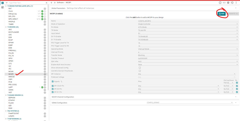
On Sitara Family of Processors, there are multiple instances of MCSPI present.
Some of the MCSPI instances are available in the MAIN Domain[example: SoC_SPI0] while few of them are from MCU Domain[example: MCU_SPI0].
Few questions from development point of view are as follows:
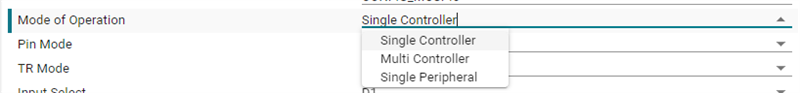
- How to configure MCSPI in MCU PLUS SDK?
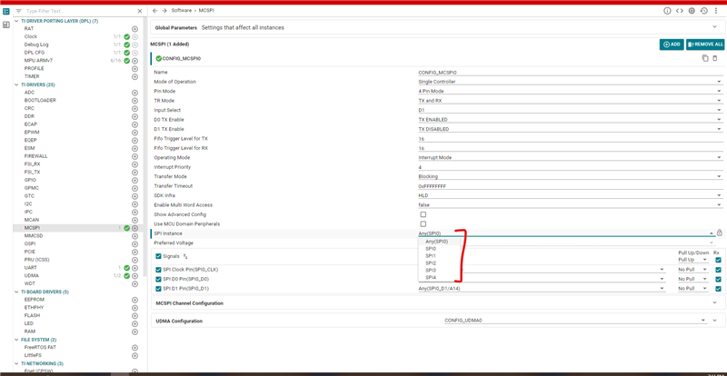
- How to configure a MCU or MAIN domain MCSPI using SysConfig tool?
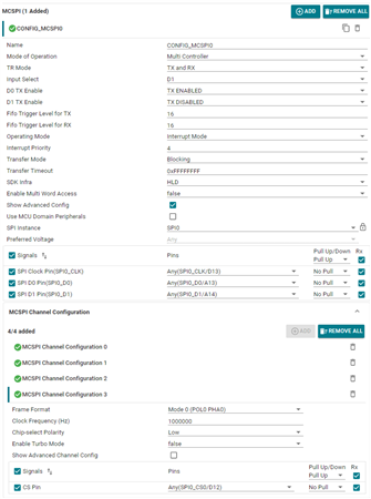
- How to configure different parameters for MCSPI?
- How to configure MCSPI as a Slave?
- How to configure chip select lines for MCSPI?
- What is the limitation on the dataSize that can be sent or received?
Let's address each of these questions.