This thread has been locked.

If you have a related question, please click the "Ask a related question" button in the top right corner. The newly created question will be automatically linked to this question.

am 3359 beaglebone black baremetal assembly programming

Other Parts Discussed in Thread: STARTERWARE-SITARA, AM3359

I am trying few things on beaglebone black. I want to do ARM assembly programming on this board without using Linux. So i pressed SW2 on the board while powering it so it skips the internal booting and waits for SD card which i haven't inserted. This way i tried to avoid booting Uboot. I also created empty project using code composer studio v5.5 and following is the code that i used in the file main_code.S

.text
.global _main
.code 32
_main:
	movs r0,#500
	ldr r1,=0x44E0713c
	strt r0,[r1]
loop:
	adds r1,r0
	subs r0,#1
	bne loop
deadloop:
	b	deadloop
	.end

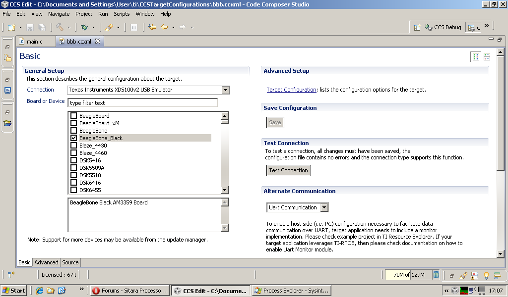
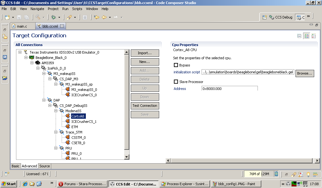
Now i also have debugger BlackHawk USB 100v2 and have selected same in project properties. when i debug this after successful build, it is in supervisor mode at start. when i do step by step debug it moves to abort mode after "strt r0,[r1]" where r1 holds the address of GPIO0 dataout register.

Also, I cannot see register values in the register tab for the same, it says "Error:Unable to read". Can anyone tell me why this happens. I would really appreciate if you could tell me way to access these memory locations to perform IO operations in assembly and without the Linux booting.

  • I get this on the console if i try to see what' s in memory using memory viewer : "CortxA8: Trouble Writing Memory Block at 0x44E0713C on Page 0 of Length 0x4: (Error -1065 @ 0x44E0713C) Unable to access device memory" and "CortxA8: Trouble Writing Memory Block at 0x44e0713c on Page 0 of Length 0x4: (Error -1065 @ 0x44E0713C) Unable to access device memory."

  • Hi Sanket,

    You are trying to access the GPIO0_DATAOUT register, right? Probably some initialization is missing. I suggest you download the Starterware software package and use it as a starting point for writing baremetal code: http://www.ti.com/tool/starterware-sitara

  • yes that's right. i need to initialize the GPIO control register. but since i want to be output pin its reset value does the part for me.

  • sanket borhade said:
    So i pressed SW2 on the board while powering it so it skips the internal booting and waits for SD card which i haven't inserted. This way i tried to avoid booting Uboot. I also created empty project using code composer studio v5.5 and following is the code that i used in the file main_code.S

    Now i also have debugger BlackHawk USB 100v2 and have selected same in project properties.

    If you stop uboot from running then a GEL script is needed in the CCS configuration file to initialize the hardware, e.g. to configure the DDR3 interface.

    If you create a target configuration for the "BeagleBone_Black" board:

    It should select a gel file to initialize the hardware:

    Is there a GEL file in your target  configuration?

  • yes, it does have gel file. I also checked the contents of the file and it says this :

    OnTargetConnect()
    {
        GEL_MapOff();
        GEL_MapReset();
        GEL_MapAddStr(0x00020000, 0, 0x0000C000, "R", 0);    // Boot ROM
        GEL_MapAddStr(0x08000000, 0, 0x01000000, "R|W", 0);  // 16MB GPMC External/NOR (on GP Daughtercard)
        GEL_MapAddStr(0x40020000, 0, 0x0000C000, "R", 0);    // Boot ROM (also at 0x20000)
        GEL_MapAddStr(0x402F0400, 0, 0x0000FC00, "R|W", 0);  // SRAM Internal
        GEL_MapAddStr(0x40300000, 0, 0x00010000, "R|W", 0);  // OCMC-RAM
        GEL_MapAddStr(0x44000000, 0, 0x00400000, "R|W", 0);  // L3F CFG Regs
        GEL_MapAddStr(0x44800000, 0, 0x00400000, "R|W", 0);  // L3S CFG Regs
        GEL_MapAddStr(0x44C00000, 0, 0x00400000, "R|W", 0);  // L4_WKUP
        GEL_MapAddStr(0x46000000, 0, 0x00400000, "R|W", 0);  // McASP0 Data
        GEL_MapAddStr(0x46400000, 0, 0x00400000, "R|W", 0);  // McASP1 Data
        GEL_MapAddStr(0x47400000, 0, 0x00005000, "R|W", 0);  // USB0/1
        GEL_MapAddStr(0x47810000, 0, 0x00010000, "R|W", 0);  // MMCHS2
        GEL_MapAddStr(0x48000000, 0, 0x01000000, "R|W", 0);  // L4 PER
        GEL_MapAddStr(0x49000000, 0, 0x00B00000, "R|W", 0);  // EDMA
        GEL_MapAddStr(0x4A000000, 0, 0x01000000, "R|W", 0);  // L4_FAST
        GEL_MapAddStr(0x4C000000, 0, 0x01000000, "R|W", 0);  // EMIF
        GEL_MapAddStr(0x50000000, 0, 0x01000000, "R|W", 0);  // GPMC Regs
        GEL_MapAddStr(0x56000000, 0, 0x01000000, "R|W", 0);  // SGX530
        GEL_MapAddStr(0x80000000, 0, 0x20000000, "R|W", 0);  // 512MB DDR3 external memory
        GEL_MapOn();
        AM335xStartState();
        AM335x_BeagleBlack_Initialization();
        Disable_Watchdog();
    
    }
    

    from this i can see that address of the GPIO's are already given "R/W" access. but still i cannot read them from the code.

  • sanket borhade said:
    from this i can see that address of the GPIO's are already given "R/W" access. but still i cannot read them from the code

    The AM335x ARM® Cortex™-A8 Microprocessors (MPUs) Technical Reference Manual SPRUH73J shows that at device reset the GPIO0 MODULEMODE is disabled - meaning any attempt to access the GPIO registers will result in an error. See the description of the CM_WKUP_GPIO0_CLKCTRL Register for details. To access the GPIO0 registers you will first need to set the MODULEMODE in the CM_WKUP_GPIO0_CLKCTRL register to 0x2 = ENABLE.

    [The same applies for the CM_WKUP_GPIO1_CLKCTRL .. CM_WKUP_GPIO3_CLKCTRL registers for GPIO1 to GPIO3]

    As Biser Gatchev-XID has already suggested, look at the StarterWare software package to see how that enables and uses the GPIO modules.

  • thanks for the reply. The example using starterWare to blink user LED on the board works fine. But its C program in the end. I need it to be done using simple ARM Assembly. So i tried to do the same process as the sample example does in Assembly, since i am not able to access the memory location of the GPIO registers i cannot enable the CLK of the module. I hope you are getting my question. (I do not want any C code in my project just Assembly programming).

  • It's great you've got the c-code blinky program working. I would suggest your next step might be to look at the C code startup file to see how they do all their initial setup.

  • I haven't done any baremetal programming on the am335x yet, but I do on the dm814x.  These chips have a fair bit of power management, and after reset most of the chip will still be unclocked or even powered off.  To get anything done, you'll need to change some registers in the PRCM (Power/Reset/Clock Manager) module to wake up clock domains and enable modules.  Many modules may then need additional enabling/configuration, but if power/clock isn't provided to the module you won't even be able to communicate with it, which is the problem you've seeing.

    The CM_WKUP_GPIO0_CLKCTRL register (0x44e00408) Chester Gillon mentioned is such a clock-enable register.  So you'll need something like this: (untested!)

            mov     r0, #2
            ldr     r1, =0x44e00408 // CM_WKUP_GPIO0_CLKCTRL
            strb    r0, [r1]        // enable module
    wait_GPIO0_ready:
            ldr     r0, [r1]
            tst     r0, #0x30000    // check idle status bits
            bne     wait_GPIO0_ready
    

    You should then be able to access the GPIO0 registers, hopefully.  Then enable output (GPIO_OE) and you should be able to control the outputs.  BTW, I see you're setting GPIO0.8 and 0.10, corresponding to LCD_DATA12 and LCD_DATA14. Just checking, that's intentional? (i.e. you have leds connected to the corresponding expansion connector pins)  If you're trying to control the on-board LEDs of the BeagleBone Black, those are located on GPIO1.21 - 24.

    If your intention is to control the on-board leds

    from this i can see that address of the GPIO's are already given "R/W" access. but still i cannot read them from the code

    The GEL_MapAddStr command in a GEL file is merely part of setting up the memory map for the debugger.  It has no actual effect on your target.  GEL files can (but do not necessarily) also contain target reads/writes to perform some setup, though you'll probably want to avoid those sooner or later and make your code able to start without the help of a GEL file.  Of course they're still useful to study which initialization steps may be needed.

  • Thanks, i will try this out and share the results.
    I have connected separate external LED's on GPIO0 for testing.

  • Good luck!

    Final word of caution:  do be very careful with the GPIO_OE register.  The am335x pinmux (unlike that of e.g. the dm814x) doesn't have a "safe mode" and configures most pins to GPIO by default.  I think this is an unfortunate design choice made by TI.  While this saves you from having to do any pin setup to get your LED or other GPIO working, it also means that if you make a mistake in GPIO_OE you end up driving the wrong pin(s), hence risk hardware damage.

  • I tried the way you suggested. I could see the contains of GPIO atleast on debugger register view by modifying the CM_WLK_GPIO0_CTRL register. But beaglebone's AM3359 is not giving access through code.
    it skips the code steps (one that you mentioned to modify register and checking the bits) and console shows error that you cannot access readonly memory locations.

    I modified the contains from CCS windows by clicking on the same and i could modify it. Then what is stopping it from doing it through code?
    I am still not sure whether i can bypass the linux booting? I would really appreciate if someone suggest method to avoid booting linux.

    probably, that is rejecting the access to these registers!

  • I added the code for enabling of modules in the gel file so that i need not do it every time at start of the code.

    this way i get all modules enabled every debug session. And by modifying the gel file i can provide access to various memory addresses too.