Greetings
First, my apologies for the long post but we have a few questions about LDC ESD that we would like clarification on.
So we will try to be as concise as possible.
Background
Application Description
For our application, we use the LDC1614 device to determine when the end user places or removes metal targets from a surface.
Both the LDC1614 and the 4 sensor coils are on the same PCB.
The target metal is 1mm away from the sensor when placed on the surface.
Finally, the end user may have the surface near high voltage ESD sources.
ESD Tests
While testing our application unit, we notice that it is currently susceptible to ESD failure when we touch the target metal while it’s on the surface.
It seems that the ESD is going from the target metal, passing through the 1mm gap, and into the sensor coil.
Using an IEC compatible ESD gun, the unit sometimes passes, and other times fails a 1kV contact discharge test.
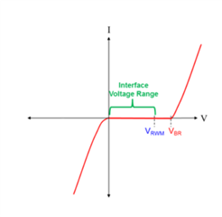
However, in section 6.2 of the datasheet, the ESD Ratings using the CDM and HBM models are ±750V and ±2000V respectively.
End Goal
We would like to be able to support ESD discharge voltages above the level 4 IEC-61000-4-2 standard voltages.
For reference, these test voltage values are 8kv and 15kV for contact discharge and air discharge respectively.
This needs to be achieved without changing the material between the sensor and target, and we have no control of when the unit will be placed by the end user.
Questions
Part 1
Currently we have a few of our application units in the hands of end users where ESD is not a major issue, but the units fail occasionally.
As a work around, we reboot the LDC1614, which is not a good long term solution.
In the short term though, it gives us some time to implement and test some ESD hardware options.
According to the datasheet, CDM and HBM tests have been done with the device to guarantee that it works within its specification.
With this in mind, we have the following questions about the device's ability to resist damage due to ESD voltages above these CDM and HBM ratings:
- Any idea (no guarantees) how long we may expect the LDC1614 device on these units to last in an ESD environment without extra external ESD protection?
- Any idea how many times on average (or minimum and maximum range of times) may the chip be hit before we can expect it to fail?
- Do you have any stress test data to determine how many times the device can be shocked above the rated values before is fails using the HBM, CBM?
- Do you have any data to show the robustness of the ESD protection?
Part 2
We were looking through the TI e2e sensors forum to look for ESD protection options for the sensor coils connected to the LDC1614 with minimal effect on sensor performance.
There we found 4 possible solutions as follows:
- Place an ESD ground shield - with reference to section 2.1.2 “Coil Shielding” on page 3 in the https://www.ti.com/lit/an/snoa962/snoa962.pdf document.
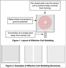
- ESD ground shielding layout options shown above
- Placing series capacitors - refer to the last 2 comments on the LDC3114-Q1: EMC and ESD protection - Sensors forum - Sensors - TI E2E support forums thread.
- Placing ESD diode - according to last comment on the LDC2114EVM: ESD from an equipment - Sensors forum - Sensors - TI E2E support forums thread.
- Placing external clamps/TVS - see ESD protection of LDC1000 inductance - Sensors forum - Sensors - TI E2E support forums thread
- This thread refers to using TVS with the LDC1000 devices.
- It recommends "lower voltage clamps/TVS at 4V" that "will have to be fast to avoid affecting the frequency count".
- However, we found that there are differences between the LDC1000 and LDC1614 as described in the table below.
-
Device
LDC1000
LDC1614
Internal ESD Clamp
5V
1.8V
Frequency Counter (CLK)
8MHz
40MHz
With reference to these 4 possible solutions, we would like some additional information on their ESD protection performance and their effects on the sensor coils.
Therefore, we have the following questions:
- For option 1 - ESD ground shielding. Snoa962 mentions that it "can also be helpful to shield the sensor coil from picking up strong E-field emissions nearby". So:
- How effective is the ESD ground shielding?
- Do you have any measurement data showing the maximum ESD peak voltage transients it is able to support?
- Will it be able to protect the device from level 4 IEC model tests?
- For option 2 - placing series capacitors:
- Will this method work with LDC1614 sensor coils?
- If so:
- What are the differences (if any) between its implementation on LDC3114 sensors and LDC1614 sensors?
- What impacts will it have on sensor performance?
- If not:
- For understand purposes, why can't it be implemented?
- For option 3 - Placing ESD diodes. In the thread, it is mentioned that you "don't recommend this since external diodes have an AC resistance that will impact the sensor performance". So:
- Can this method be used with the LDC1614 on its sensor traces?
- Are there any other diode characteristics besides AC resistance (such as capacitance, etc) that will impact sensor performance?
- Are there any ESD diodes that we may be able to consider?
- For option 4 - Placing external clamps/TVS.
- Will this method work with the LDC1614 sensors?
- If it can be used, are there any TVS devices you can recommend?
- With reference to the above table, is it correct to say we need clamps/TVS components with a voltage lower than 1.8V, and turn on faster than the 40MHz clock?
- Additional options:
- Can any of these options be combined in any way?
- Are there any alternative options or ideas?
Thanks for your time.
Cheers
JC