Other Parts Discussed in Thread: IWR6843ISK, IWR6843AOP, MMWAVE-STUDIO, MMWAVEICBOOST, IWR1843BOOST, SK-TDA4VM, TDA4VM, DCA1000EVM
Tool/software:
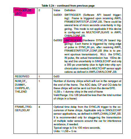
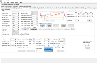
I am looking to trigger the frame capture of the IWR6843AOPEVM as I have seen several people have successfully done that.
For instance, [with IWR6843AOPEVM here](https://e2e.ti.com/support/sensors-group/sensors/f/sensors-forum/1231464/iwr6843aopevm-hardware-triggering-sync_in-pulse-requirements)
and [with IWR6843ISK here](https://e2e.ti.com/support/sensors-group/sensors/f/sensors-forum/1039687/mmwaveicboost-mmwave-studio-calling_connecttarget-returned-3-error)
and [with IWR6843ISK again](https://e2e.ti.com/support/sensors-group/sensors/f/sensors-forum/972613/iwr6843isk-hardware-trigger ).
I have gone through these discussions, the relevant SDK link, and the schematics for IWR6843AOP.
But I still have some upfront questions.
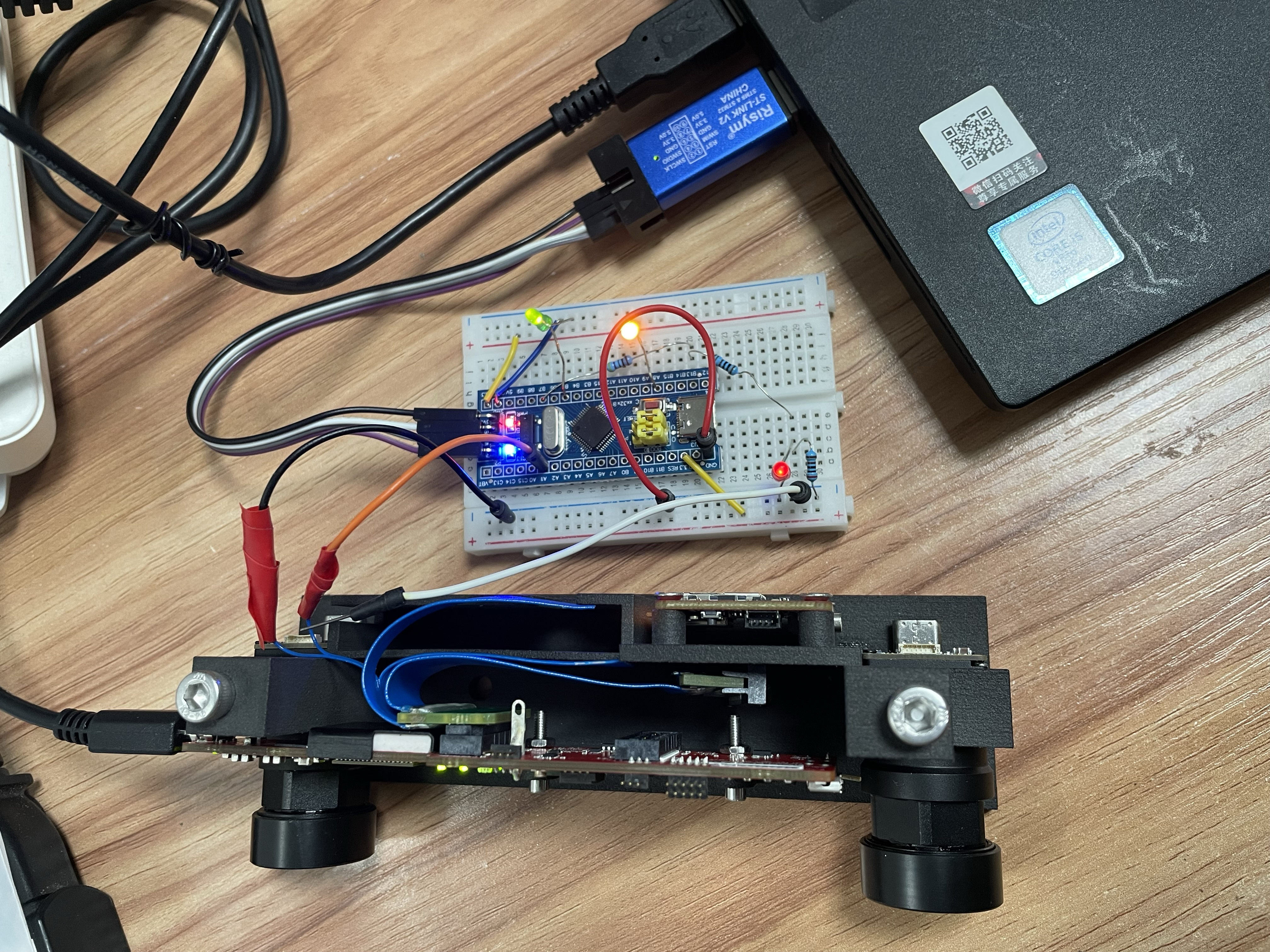
1. where is the SYNC_IN pin on IWR6843AOPEVM if it exists? Do I need a DCA boost carrier board for sync?
2. I have seen some post about replacing resistors from the DCA carrier board for sync, I guess we don't need to do that for IWR6843AOPEVM, right?
3. We need 3.3V PWM signals to SYNC_IN, right?
Thank you for your clarification,