The TI E2E™ design support forums will undergo maintenance from July 11 to July 13. If you need design support during this time, open a new support request with our customer support center.

This thread has been locked.

If you have a related question, please click the "Ask a related question" button in the top right corner. The newly created question will be automatically linked to this question.

AWR1642: About DCA1000 FT4232 EEPROM issue

Part Number: AWR1642

Hi SIr 

Due to design requirement, we add one FT4232 in our debug board in order to use mmwave studio.

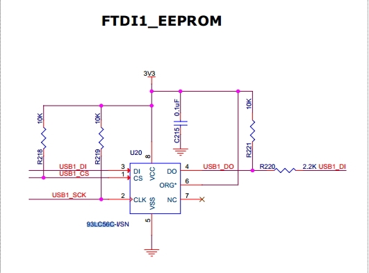
in the schematic , FT4232 has one external EEPROM (same with DCA1000 schematic). Dose TI have the firmware to program it or any other document about the internal data for programming.

thanks in advance.

BR

Yimin

  • 0310.AR-DevPack-EVM-012.xml
    <?xml version="1.0" encoding="utf-16"?>
    <FT_EEPROM>
      <Chip_Details>
        <Type>FT4232H</Type>
      </Chip_Details>
      <USB_Device_Descriptor>
        <VID_PID>2</VID_PID>
        <idVendor>0451</idVendor>
        <idProduct>FD03</idProduct>
        <bcdUSB>USB 2.0</bcdUSB>
      </USB_Device_Descriptor>
      <USB_Config_Descriptor>
        <bmAttributes>
          <RemoteWakeupEnabled>false</RemoteWakeupEnabled>
          <SelfPowered>false</SelfPowered>
          <BusPowered>true</BusPowered>
        </bmAttributes>
        <IOpullDown>false</IOpullDown>
        <MaxPower>100</MaxPower>
      </USB_Config_Descriptor>
      <USB_String_Descriptors>
        <Manufacturer>FTDI</Manufacturer>
        <Product_Description>AR-DevPack-EVM-012</Product_Description>
        <SerialNumber_Enabled>true</SerialNumber_Enabled>
        <SerialNumber />
        <SerialNumberPrefix>FT</SerialNumberPrefix>
        <SerialNumber_AutoGenerate>true</SerialNumber_AutoGenerate>
      </USB_String_Descriptors>
      <Hardware_Specific>
        <TPRDRV>0</TPRDRV>
        <Port_A>
          <VCP>true</VCP>
          <D2XX>false</D2XX>
          <RI_RS485>false</RI_RS485>
        </Port_A>
        <Port_B>
          <VCP>true</VCP>
          <D2XX>false</D2XX>
          <RI_RS485>false</RI_RS485>
        </Port_B>
        <Port_C>
          <VCP>true</VCP>
          <D2XX>false</D2XX>
          <RI_RS485>false</RI_RS485>
        </Port_C>
        <Port_D>
          <VCP>true</VCP>
          <D2XX>false</D2XX>
          <RI_RS485>false</RI_RS485>
        </Port_D>
        <IO_Pins>
          <Group_A>
            <SlowSlew>false</SlowSlew>
            <Schmitt>false</Schmitt>
            <Drive>4mA</Drive>
          </Group_A>
          <Group_B>
            <SlowSlew>false</SlowSlew>
            <Schmitt>false</Schmitt>
            <Drive>4mA</Drive>
          </Group_B>
          <Group_C>
            <SlowSlew>false</SlowSlew>
            <Schmitt>false</Schmitt>
            <Drive>4mA</Drive>
          </Group_C>
          <Group_D>
            <SlowSlew>false</SlowSlew>
            <Schmitt>false</Schmitt>
            <Drive>4mA</Drive>
          </Group_D>
        </IO_Pins>
      </Hardware_Specific>
    </FT_EEPROM>
    Hello Yimin,

    Its not a firmware but what you need is a FTDI template to be loaded onto the EEPROM. Attached is the EEPROM template you can use if you follow the exact same pin definition of the FTDI chip as used in the DCA1000.

    Regards,

    Vivek