

Hello Everyone,
Please see the below Frequently Asked Questions on the IWR6843 AoP Device and IWR6843AOPEVM.
Cheers,
Akash

This thread has been locked.
If you have a related question, please click the "Ask a related question" button in the top right corner. The newly created question will be automatically linked to this question.
Hello Everyone,
Please see the below Frequently Asked Questions on the IWR6843 AoP Device and IWR6843AOPEVM.
Cheers,
Akash
Thanks for the information.
-Nitin

Frequently Asked Questions on the IWR6843AoPEVM:
Antenna Questions:
Q: How deep in the chip is the antenna located (in order to find proper distance for cover placement)? Is there any material interface (through which waves are passing) on the top of the chip that should be taken in account?
A: Antenna is located on the Top side of the Package itself. There is no material interface, Antennas are located on the top surface of the package. Hence for the distance measurement you could consider top side of the package.
Q: Is it possible to place cover directly in contact with the chip front? Or should there be at least half wavelength gap?
A: It's recommended to keep at-least multiple of half wavelength distance. Please refer to this app-note section 5.
Q: How does Angular Resolution compare from AoP to ISK antenna?
A: IWR6843AOP has different antenna configuration, hence it has equal angular resolution both in Azimuth and Elevation direction.
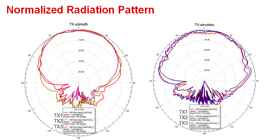
Q: What is the antenna pattern for IWR6843AoPEVM?
A: Rx Pattern:

Tx Pattern:
Q: What is the arrangement of Transmitters and Receivers on IWR6843AOPEVM?

Below diagram has the antenna placement and positions of virtual Antenna pairs.

Schematics:
Q: Are schematics of the IWR6843AOPEVM available?
A: Yes they are! You can find schematic, assembly, and BOM on the IWR6843AOP Landing Page under the Design Files Section.
Visualizer Error:
Q: When I am trying to connect send config to mmWave device, then it is showing an error "Selected Platform [xWR68xx_AOP] not matching that reported by target [xWR68xx]".
A: This error occurs when the AoP EVM has been flashed with binaries from the Non-AoP SDK. You should instead flash the EVM with 64xx_AoP binary from the appropriate AoP SDK.
EVM Questions:
Q: Do I need to purchase an MMWAVEICBOOST Carrier card with my AoP EVM?
A: The MMWAVEICBOOST is highly recommend for development and debug purposes. The board provides debug, raw data capture connectivity, SPI and interface to the antenna board peripherals etc. whereas in standalone mode you have access to UART, you can flash the EVM and get data out of the UART port.
Q: Is Heat Sink necessary for IWR6843AoPEVM?
A: Heat sink is not a mandatory requirement for the EVM. However, EVM comes with the example heat sink option for the EVM, Heat sink helps in reducing the junction temperature. Below curve shows duty-cycle vs temperature in deg centigrade. There are four curves two of them shows temperature difference with and without heat sink options. Other two curves are best fit linear trend lines for the with and without heat sink options. Below graph is specific example of heat sink and customers could choose to design their own heat sink depending upon their application needs. Also customers could choose to operate different duty-cycle options depending upon the application requirements.care need to be taken not to exceed the junction temperature beyond 105 deg C.

Q: What other boards do I need to use IWR6843AoPEVM
AoPEVM could be used standalone configuration, in this case one could flash the EVM and run demo applications.
Extended section of the EVM allows connectivity to other chipsets such as Bluetooth, 9-Axis sensor, LCD interfaces. Note that some of these components are not pre-mounted along with the EVM, customer need to mount these components.
60Pin connector on the back side of the board allows connectivity to MMWAVEICBOOST from which customers could connect to XDS110 interface/14 pin/60 pin MIPI connector for JTAG and other advanced debugging options.
With the help of Carrier board (MMWAVEICBOOST, DCA1000 and IWR6843AoPEVM) raw ADC data could be captured using mmWave studio application.
For more details please refer to EVM user-guide.
Q: How can I use the break out board part of the IWR6843AoPEVM and implications?
EVM is designed for form-factor usage, Customers could choose to breakout section to separate the EVMs into two pieces. Once EVMs are separated it cannot be joined together.
After the break-away EVM module would be 23 x 22 mm size. This section offers one USB connector and slide switch for flashing mode and default functional mode options.
Care need to be taken on the thermal heat dissipation, at higher duty-cycle heat sink option need to be considered so that junction temperature should not exeeded 105 deg C.
Q: What Demos are available for IWR6843AoPEVM ?
The following demos are available for IWR6843AOPEVM
Q: Can I run IWR6843ISK code on IWR6843AoPEVM ? How?
Compared to the IWR6843ISK, the IWR6843AOPEVM has a different antenna design and this requires modifications to the angle of arrival computation corresponding to the IWR6843AOPEVM virtual antenna array.
To develop basic understanding of virtual antenna arrays and angle of arrival estimation concepts, refer to the following resources
The IWR6843AOPEVM is supported by mmWave SDK 3.2.0.x_AOP which provides the 2D AoA DPU (Data Processing Unit) for angle of arrival estimation on the AOP device. This AoA technique is not supported in mmWave SDK 3.2.0.x for IWR6843ISK so the user will need to modify/replace the angle of arrival code in the ISK based application according to the AoA technique demonstrated in the 2D AoA DPU used in the IWR6843AOP out of box demo.
Please refer to the following documentation resources included in mmWave SDK 3.2.0.x_AOP to understand the IWR6843AOP out of box demo and the 2D AoA technique.
MMWAVE-SDK 3.2.0.6 Module Documentation.
Frequently Asked Questions on the IWR6843AoPEVM Rev.F:
Antenna Questions:
Q: How deep in the chip is the antenna located (in order to find proper distance for cover placement)? Is there any material interface (through which waves are passing) on the top of the chip that should be taken in account?
A: Antenna is located on the Top side of the Package itself. There is no material interface, Antennas are located on the top surface of the package. Hence for the distance measurement you could consider top side of the package.
Q: Is it possible to place cover directly in contact with the chip front? Or should there be at least half wavelength gap?
A: It's recommended to keep at-least multiple of half wavelength distance. Please refer to this app-note section 5.
Q: How does Angular Resolution compare from AoP to ISK antenna?
A: IWR6843AOP has different antenna configuration, hence it has equal angular resolution both in Azimuth and Elevation direction.
Q: What is the antenna pattern for IWR6843AoPEVM?
Antenna pattern can be found in section 5.10.1 Antenna Radiation Patterns of the datasheet
Q: What is the arrangement of Transmitters and Receivers on IWR6843AOPEVM?
Details on the antenna including arrange of transmitters and Receivers can be found here
https://dev.ti.com/tirex/explore/node?node=AGMzFzzFdFllMlyaWeXNlw__VLyFKFf__LATEST
Schematics:
Q: Are schematics and layout of the IWR6843AOPEVM available?
A: Yes they are! You can find schematic, assembly, and BOM on the IWR6843AOP Landing Page under the Design Files Section. The layout and Altium source file can be found here https://www.ti.com/lit/zip/sprr418
Visualizer Error:
Q: When I am trying to connect send config to mmWave device, then it is showing an error "Selected Platform [xWR68xx_AOP] not matching that reported by target [xWR68xx]".
A: This error occurs when the AoP EVM has been flashed with binaries from the Non-AoP SDK. You should instead flash the EVM with 64xx_AoP binary from the appropriate AoP SDK.
EVM Questions:
Q: Do I need to purchase an MMWAVEICBOOST Carrier card with my AoP EVM?
A: The MMWAVEICBOOST is highly recommend for development and debug purposes. The board provides debug, raw data capture connectivity, SPI and interface to the antenna board peripherals etc. whereas in standalone mode you have access to UART, you can flash the EVM and get data out of the UART port.
Q: Is Heat Sink necessary for IWR6843AoPEVM?
A: Heat sink is not a mandatory requirement for the EVM,however the EVM comes with the heat sink installed. Care needs to be taken not to exceed the junction temperature beyond 105 deg C when using the EVM. The heat sink helps in reducing the junction temperature, customers could choose to operate different duty-cycle options depending upon the application requirements. More details on this can be found in the appnote linked below
https://www.ti.com/lit/an/swra672/swra672.pdf
Q: What other boards do I need to use IWR6843AoPEVM
AoPEVM could be used standalone configuration, in this case one could flash the EVM and run demo applications.
Extended section of the EVM allows connectivity to other chipsets such as Bluetooth, 9-Axis sensor, LCD interfaces. Note that some of these components are not pre-mounted along with the EVM, customer need to mount these components.
60Pin connector on the back side of the board allows connectivity to MMWAVEICBOOST from which customers could connect to XDS110 interface/14 pin/60 pin MIPI connector for JTAG and other advanced debugging options.
With the help of Carrier board (MMWAVEICBOOST, DCA1000 and IWR6843AoPEVM) raw ADC data could be captured using mmWave studio application.
For more details please refer to EVM user-guide.
Q: How can I use the break out board part of the IWR6843AoPEVM and implications?
EVM is designed for form-factor usage, Customers could choose to breakout section to separate the EVMs into two pieces. Once EVMs are separated it cannot be joined together.
After the break-away EVM module would be 26 x 36 mm size. This section offers one USB connector and slide switch for flashing mode and default functional mode options.
Care need to be taken on the thermal heat dissipation, at higher duty-cycle heat sink option need to be considered so that junction temperature should not exeeded 105 deg C. Thermal Design guide reference above provides more details on this
Q: What Demos are available for IWR6843AoPEVM ?
The following demos are available for IWR6843AOPEVM
Q: Can I run IWR6843ISK code on IWR6843AoPEVM ? How?
Compared to the IWR6843ISK, the IWR6843AOPEVM has a different antenna design and this requires modifications to the angle of arrival computation corresponding to the IWR6843AOPEVM virtual antenna array.
To develop basic understanding of virtual antenna arrays and angle of arrival estimation concepts, refer to the following resources
The IWR6843AOPEVM is supported by mmWave-SDK 03_04_00_03 which provides the angle of arrival estimation on the AOP device. This AoA technique for ISK is different than that of ISK and should be accounted in the user demo.

