

My colleague Collin Wells recently completed a blog series about 2-wire 4-20mA transmitters and their associated design challenges. The series concluded with a look at isolation schemes for 2-wire transmitters as defined by the American National Standards Institute (ANSI)/International Society of Automation (ISA)-50.1-1982 specification. After reading that post, I thought it would be beneficial to take a look at the same isolation schemes for 3-wire transmitters, which are used in the same sensor transmitter applications, except for high-power designs.
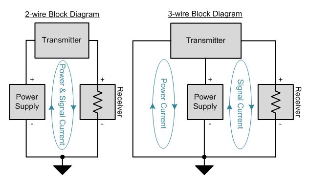
Figure 1: Simplified block diagrams of 2-wire and 3-wire transmitters
In one of my previous blog posts, I wrote about several architectures used for analog outputs in industrial automation. Figure 1 reiterates one of the key points I made in that post. As you can see, 2-wire transmitters use a single current loop for both power and ground, and therefore must consume less than 4mA of quiescent current (iq). Some sensors, however, require more than 4mA of iq and therefore the system must use a 3-wire sensor-transmitter approach, where power and signal current each flow in separate loops, allowing the sensor to consume as much current as necessary.

Figure 2: Non-isolated and input-isolated 3-wire transmitter block diagrams
Like 2-wire transmitter designs, an input-isolated scheme is sometimes required for 3-wire transmitters, usually when the sensor is conductively connected its measurement target which has a different ground potential than the PLC analog input. As illustrated in Figure 2, an input-isolated 3-wire sensor transmitter design receives power from the analog input or programmable logic controller (PLC) host. While the transmitter itself shares a ground with its host, the sensor resides on the opposite side of a digital- and power-isolation barrier.
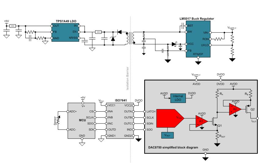
Figure 3: Input-isolated 3-wire transmitter
Figure 3 shows an example design for an input-isolated 3-wire transmitter. This design uses a DAC8750 digital-to-analog converter (DAC), powered directly from the 3-wire transmitter supply, to provide the signal chain to create the standard industrial current outputs (DAC, reference voltage and high-side voltage-to-current converter). The DAC8750 also provides an internal low-dropout regulator (LDO) to supply its own digital core along with the transmitter side of the digital-isolation barrier provided by the ISO7641. The LM5017 buck regulator provides isolated power to the sensor side of the isolation barrier, derived directly from the 3-wire transmitter supply voltage. A high power-supply rejection ratio (PSRR) LDO, the TPS7A49, is used to clean up the isolated power for use in the sensor and ADC signal chain. The isolated power section of this design is derived from the evaluation board described in the LM5017 evaluation board user’s guide.
Input isolation is sometimes also required in PLC analog-output modules, although the architectures defined by the ANSI/ISA-50.1-1982 standard no longer apply. Typically this is because the PLC backplane ground is different than the load ground that the analog-output is driving. Figure 4 shows an example design.
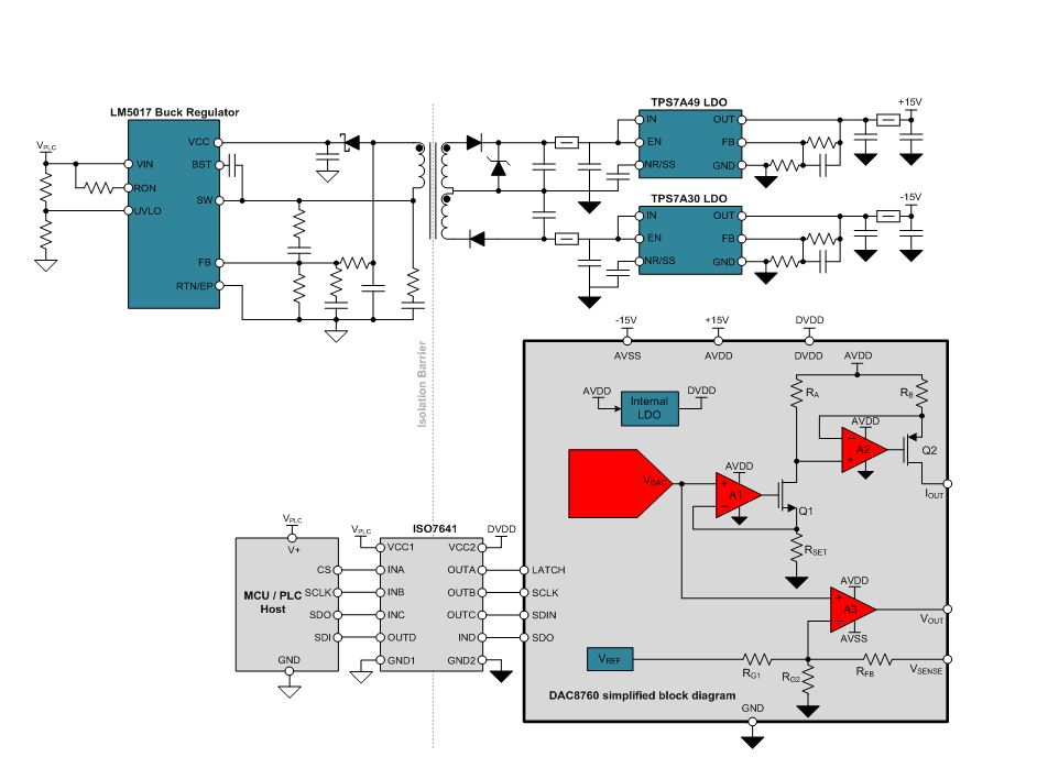
Figure 4: Input-isolated PLC analog-output module
This design uses the same buck regulator as the previous design, the LM5017, to derive dual isolated supply voltages. The isolated supplies are followed by high-PSRR LDOs (TPS7A49 for the positive rail and TPS7A30 for the negative rail) to reduce ripple and derive +/-15V supplies for use with the DAC8760, which provides complete signal chains for standard industrial voltage and current outputs. The isolated power supply in this design is based on the ultra-small 1W, 12V-36V isolated power supply for analog PLC modules TI Design reference design.
Be on the look-out for more about isolation, as well as 4-wire transmitters in upcoming posts. If there is anything you’d like to hear more about concerning isolation for analog outputs in industrial automation, post a comment below.
