

Have you ever seen the wheels on a car actually spin backward while the car is moving forward? Barring an extreme stunt, I’ll bet you probably saw it in a car commercial. Have you ever wondered why?
Real life happens in continuous time, but a video camera can only record a limited number of frames per second. Each frame may capture the wheels in a different position, so depending on how many rotations the wheels complete between frames, they might actually appear to be rotating backward as you watch the video! This effect is known as aliasing.
Data-acquisition systems using analog-to-digital converters (ADCs) experience this same phenomenon as they make discrete “snapshots” of a continuous time signal. In this post, I’ll introduce what aliasing looks like in the world of ADCs.

Figure 1: Classic example of aliasing in car commercials
What is aliasing?
According to the Nyquist theorem, an ADC must sample the input signal at least twice as fast as its highest-frequency component in order to reproduce the original signal in the digital domain – otherwise, aliases are produced. This minimum required sampling rate is known as the Nyquist rate. Or conversely, the highest-frequency signal that an ADC can accurately convert is one-half the sampling rate, known as the Nyquist frequency.
Let’s take a look at an example data-acquisition system with an ADC sampling a 6-Hz input sine wave at 7 samples-per-second (SPS). Our resulting Nyquist frequency is 3.5Hz, with any input signal frequencies greater than 3.5Hz generating aliases of the original input. Figure 2 illustrates what this looks like in the time domain using the original 6-Hz input and two of its aliases: 1Hz and 8Hz. Since all three sine waves intersect at each sample, a 6-Hz sine wave sampled at 7SPS will look no different than a 1-Hz or an 8-Hz sine wave! When we look at the output data, aliasing makes it impossible to differentiate the 6-Hz sine wave we wanted to measure from its aliases and the desired signal content is lost.

Figure 2: Aliasing in the time domain
But how could you have known that a 6-Hz sine wave would have aliases at 1Hz and 8Hz? Looking at aliasing in the frequency domain makes this more apparent. When sampled by an ADC, the frequency content of the input signal repeats itself at multiples of the sampling rate, starting at DC. Now you can see why the term “folding back” is often used to describe how signals alias – if you were to fold Figure 3 at the dotted lines, these signals would overlap each other perfectly.
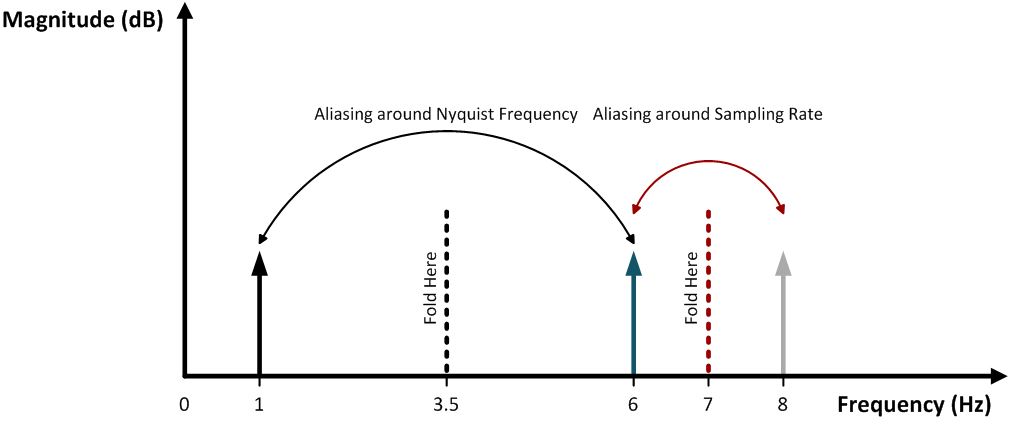
Figure 3: Aliasing in the frequency domain
To properly measure an input sine wave, the sampling rate must satisfy the Nyquist sampling criteria. In the example above, you would need to increase the sampling rate to at least 12SPS. At exactly 12SPS, the 6-Hz input will still fold back to DC and add an offset to the measurement, so sampling just a little faster ensures that your signals of interest do not alias at all.
But what about noise? White noise occurs across all frequencies, so it will undoubtedly alias from higher frequencies back into the passband between DC and the Nyquist frequency. The result is a higher in-band noise level, which will degrade important specifications like signal-to-noise ratio (SNR). Fortunately, there’s a solution for that: the anti-aliasing filter.
Anti-aliasing filters
Most ADCs are preceded by an anti-aliasing filter, which is nothing more than a low-pass filter used to attenuate signals beyond the bandwidth of interest. The response of an ideal anti-aliasing filter is perfectly flat up until the Nyquist frequency, after which it rolls off sharply to attenuate out-of-band frequencies as shown in Figure 4. Here, the sampling rate has been doubled to 14SPS, which puts the Nyquist frequency at 7Hz and the original 6-Hz input safely within the passband.

Figure 4: Frequency response of an ideal anti-aliasing filter
Designing a filter that can achieve this type of frequency response can be very challenging, often requiring active components. These extra components significantly add to the size, cost, and power consumption of the signal chain and make implementing such a filter far less ideal.
To make this easier to understand, I’ll show you in a follow-up blog how delta-sigma ADCs significantly relax the design requirements on your anti-aliasing filter. Additionally, I’ll provide some key guidelines to designing an anti-aliasing filter that’s appropriate for your application.
Additional resources
- Check out other posts by my colleagues with design tips and delta-sigma ADC basics.
- Find more than 100 data converter technical resources in our Data Converter Learning Center.
- Learn all about PGA input requirements by fellow TI applications engineer Bryan Lizon.
- Learn about TI’s data converter portfolio and find technical resources.


