

Last week we looked at the effect that internal differential input clamp diodes could have on op amps when used as a comparator. I posed a question--can these clamps affect op amp circuits. Op amps should have near zero volts between the two input terminals, right? So these diodes will never forward bias in normal op amp circuits... or will they?
Just a reminder, we’re talking about the differential clamp diodes that may be present in some op amps, see figure 1.
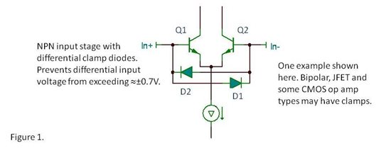
The effect in op amp circuits is often seen in the basic non-inverting amplifier configurations, including a simple G=1 buffer amplifier. Consider a positive-going input step. The output cannot immediately follow the abrupt input voltage change. If the input step is greater than 0.7V, D1 will conduct, disturbing the non-inverting input. During this period when the op amp is slewing to its new output voltage, the current in the input terminal of the op amp will spike to a much higher value, see figure2. Eventually, when the output “catches up” to the input and all will be well again.
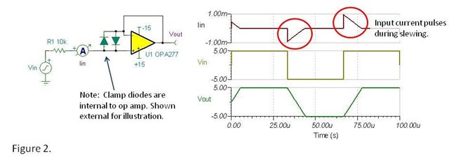
Many applications process inherently slow or band-limited signals, well below the slew rate of the op amp so this behavior would never occur. And in other applications, even with fast changing input voltage, the transient in input terminal current does not adversely affect circuit operation. But in some special cases, the pulse of input current can cause problems. One noteworthy situation is in a multiplexed data acquisition system--a simplified case just showing two input channels is shown below.
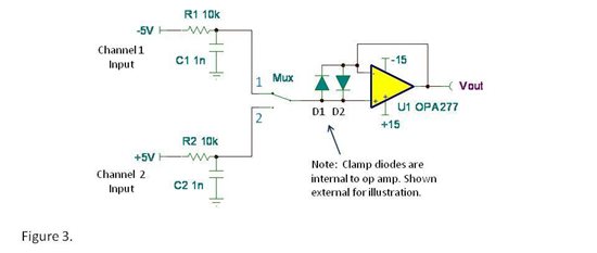
As the multiplexer switches from channel 1 to channel 2, in this example, U1’s output is required to quickly slew from -5V to +5V. D1 forward biases and the resulting input current transient passes through the multiplexer switch, discharging the voltage on C2. R/C input filters are often used to hold a steady voltage during channel switching but the current pulse partially discharges C2. It will now take additional time for C2 to recharge to the correct input voltage thus slowing down the possible multiplex rate or reducing accuracy.
The solution is to use an op amp without differential clamps for U1. A FET-input amplifier such as the OPA140 has low input bias current (so as to not load the series resistance of the MUX) and no differential input clamps. It’s great for multiplexed inputs. The OPA827 is an extraordinary performer in most applications--FET input, very low noise, high speed and fast settling. But it has differential input clamps so the OPA827 is probably not the best choice for the op amp following a multiplexer. Last week’s blog had some general guidelines on various op amp types with focus on differential clamps. Check it out for more details… Op Amps as Comparators.
I certainly don't want to leave an impression that op amps with differential input clamps are risky and should be avoided. They are not. But with awareness, you can make better-informed selections in the rare instances where they could affect your circuits. Have you found other ways that differential input clamps affect your circuits?
Thanks for reading,
Bruce

