

Do you add a resistor to match the DC resistance at the inputs of your op amp circuits? Check the circuits in figure 1 below. Many of us were instructed to add Rb as “good practice,” making its value equal to the parallel combination of R1 and R2. Let’s look at the reason for this resistor and consider when it’s appropriate and when not.
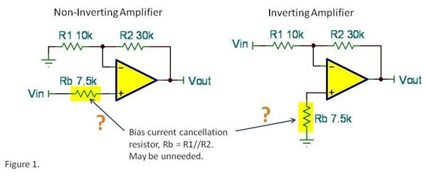
The purpose of Rb is to reduce the voltage offset caused by input bias current. If both inputs have the same input bias current, equal current flowing through equal resistances will create equal and opposite offset voltages. Thus, input bias current will not contribute to the offset voltage of the circuit. The basic idea is has merit in some instances. But before adding Rb, is it always necessary?
Many times, the parallel resistance of R1 and R2 is low enough and input bias current is low enough that the offset created without Rb is insignificant. Before adding this resistor, calculate the error. Let’s assume for this application that the input bias current of the op amp is 10nA. Without using Rb, the input-referred offset voltage due to input bias current will be…
Input offset Voltage due to Ib = (10nA) (7.5kΩ) = 75uV
Will 75uV of input offset affect your circuit? Many times the answer will be no, so why add the resistor. Consider the offset voltage of the op amp you are using. It may be pointless to be concerned with 75uV if, for example, the offset voltage specification of your op amp is1mV. So compare the error produced by input bias current to the offset voltage specification before routinely adding Rb to your circuit.
Transimpedance applications often use high feedback resistor values to amplify very small currents. Here again, you may be tempted to add Rb to balance the resistance at both inputs. But these applications generally use FET or CMOS-input op amps. With their very low input bias current, offset error is generally very small.
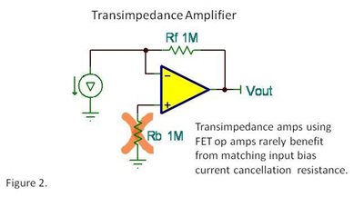
Thermal noise produced by Rb and possible external noise pickup at this high impedance node may be additional reasons to eliminate Rb. With minimal error from input bias current, why add possible noise to the circuit?
There may occasionally be a clear and valid case for using a bias current cancellation resistor. But many circuits derive no significant benefit and may even suffer reduced performance. We will revisit this issue next week to consider certain op amps that never need bias current cancellation resistors.
Comments welcome and thanks for reading,
Bruce


