

Bode plots are great analytical tools but you may not find them intuitive. This is a purely intuitive look at frequently encountered causes for op amp instability and oscillations.
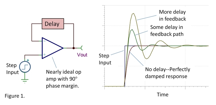
The perfectly damped response in figure 1 occurs with no delay in the feedback signal reaching the inverting input. The op amp responds by ramping toward the final value, gently slowing down as the feedback signal detects closure on the proper output voltage.
Problems develop when the feedback signal is delayed. With delay in the loop, the amplifier does not immediately detect its progress toward the final value. It overreacts by racing too quickly toward the proper output voltage. Note the faster initial ramp rate with delayed feedback. The inverting input fails to receive timely feedback that it reached and passed the proper output voltage. It overshoots its mark and requires several successively smaller polarity corrections before finally settling.
A little delay and you merely get some overshoot and ringing. Too much delay and these polarity corrections continue indefinitely—an oscillator.
The source of delay is often a simple low-pass R-C network. Okay, it’s not a constant delay for all frequencies but the gradual phase shift of this network from 0° to 90° produces a first-order approximation of time delay, td=RC.
There are two commonly encountered situations where this R-C network unintentionally sneaks into our circuits. The first is with a capacitive load (figure 2a). The resistor is the op amp’s open-loop output resistance. The capacitor is, of course, the load capacitance.
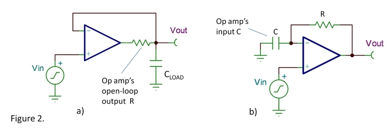
In the second case (figure 2b), the feedback resistance and the op amp’s input capacitance form the R-C network. Circuit board connections also contribute to the capacitance at this sensitive circuit node. Note that the two circuits have identical feedback loops. The only difference is the node at which the output is taken. From a loop stability standpoint, they can create the same issues. And these two causes of delayed feedback often occur in combination—a bit of both can be double trouble.
The second case needs a bit more comment: A feedback resistor is not needed for the simple G=1 buffer so the more common situation is in a gain configuration using a feedback resistor and resistor to ground (figure 3). The parallel combination of these resistors forms the effective R in the R/C circuit.

There’s more to be learned with Bode analysis of feedback amplifiers. Still, this simple intuitive view of how delay or phase shift in the feedback path affects stability can help you diagnose and solve the most common stability problems. More later on how to deal with these problems.
Thanks for reading,
Bruce
