

My colleague Soufiane recently published an article, “Pushing the Precision Envelope.” In it, he discussed various technologies we use to “trim” or adjust the offset voltage of our amplifiers to very low values. It got me thinking about offset voltage trim pins—where did they go?
Most newer op amps lack the offset voltage trim pins once found on virtually all op amps. There are many factors at work in this change. Better, lower offset amplifiers, auto-calibrated system designs, pressure to reduce assembly and adjustment costs, tiny surface-mount packages—all combine to reduce the use of offset trim pins. Still, many of our best selling op amps have trim pins and knowledge and best practices of how to use (or not use) them are fading.
This much is easy—if you don’t use the trim pins, leave them open-circuit, no connection—do not connect them to ground.
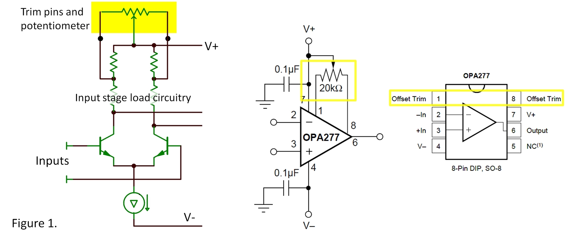
Figure 1 shows a common type of internal trim circuitry. Trim pins connect to a tapped portion of the input stage load circuitry. Adjusting the potentiometer skews the balance of the load ± a few millivolts of input offset voltage. Data sheets generally recommend a value for the pot but it is not critical. A much higher resistance potentiometer will cause the change in offset voltage to occur toward the extremes of rotation. Too low a value will reduce the adjustment range. Pots in the range of +100% to -50% of the recommended value will likely function satisfactorily.
Notice that the trim circuitry in this example is referenced to the V+ supply. Some op amps have trim circuitry referenced to the V- supply terminal. Connecting the wiper of the pot to the wrong rail or to ground on a ± supply will surely cause problems. Some designers attempt tricky active circuitry to drive these pins. While this is possible, ground-referred circuitry connected to the trim pins can create power supply rejection problems.
It’s best to use the trim pins only to null the offset of the first amplifier in a signal chain. Generally that stage has some gain and its offset dominates that of the complete signal chain. If used to correct other large sources of offset in the chain, you could introduce an unwanted temperature drift.
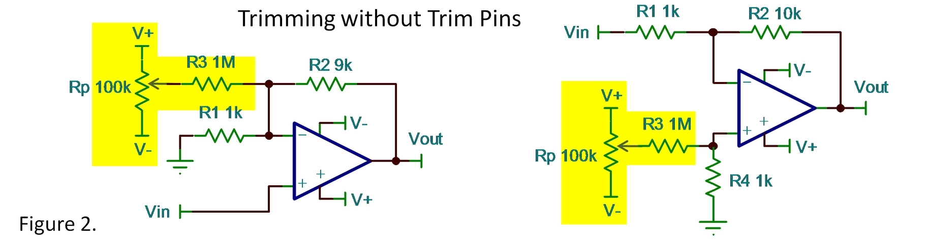
Lacking trim pins, there are other ways to trim offsets in your system. Variable voltages from a potentiometer or other control signal can be injected or summed into various points in your signal chain. Examples are shown in figure 2. Notice that these trimming voltages are shown here to be derived from the power supplies. Regulated supplies are probably sufficient. Unregulated supplies such as batteries may not be sufficiently constant or stable.
The improved offset voltage of modern amplifiers often eliminates the need for trimming. Still, there are times when some type of offset adjustment is required. You can be ready with techniques, whether with trim pins or add-on circuitry.
Do you trim offset voltage? How? Please tell us in your comments below?
Bruce email: thesignal@list.ti.com
Index to all The Signal blogs.

