This thread has been locked.

If you have a related question, please click the "Ask a related question" button in the top right corner. The newly created question will be automatically linked to this question.

CC2510 Range

Other Parts Discussed in Thread: CC2511, CC2510, CC2500

Hi all,

I was hoping you could help me with a problem I'm having. In my current design I have a CC2510 on a small pcb with a chip antenna. It is communicating with a CC2511 dongle. Normally I have about 40-50cm range. When I put the device in a plastic housing with the lithium polymer battery that is powering it the range decreases to almost 2cm. I have found that by keeping the battery out of the enclosure the range is about 30cm so it appears that by having the battery in the enclosure with the CC2510 the range is severly decreased.

The layout of the system is as follows:

  1. Plastic lid on top
  2. Battery below this
  3. Underside of PCB below this
  4. CC2510 on other side of this PCB, i.e. not touching the battery.
  5. Plastic lid on bottom.

The plastic is only about 2mm thick and the battery is only about 4mm thick.

Any ideas why this would be happening??

Thanks,

Dave

  • First you write   "...I have about 40-50cm range,"  This is very short even with a chip antenna. I would expect something over 15 to 20 meters at full output power.

    Is the antenna on the same side as the chip? That is between the PCB ground plane and the bottom and whatever the unit is setting on? It sounds like the battery is on the back side of the board and isolated from the antenna by the board's ground plane where there should not be any impact. This assumes the chip antenna is on the same side as the Ti chip and the battery is not placed directly below the antenna. If the battery is directly below it, it will transform the antenna into just another length of transmission line over a ground plane where radiation will be minimal. T-lines over ground plane are low loss exactly because they do not radiate.

      |   Battery   |
    ---------------------------  -  -  -  -  -  -            -  -  -  -  -  -  =  no copper
    ---------------------------  -  -  -  -  -  -
       |Chip|                         |   Ant   |

    Li-Ion batteries generally have metal jackets for safety reasons. A large metal plane near, but not directly under,  the antenna could have a major impact on the antenna pattern. Imagine a large reflector spaced such that the reflected signal was 180 out of phase with the Tx signal therefore canceling the Tx signal.  

    The battery case is not adsorptive at these frequencies provided the coupling isn’t into the battery via its leads.

    A picture would help…


  • Hi and thanks for answering,

    Unfortunately I don't have a digital camera with me today but my PCB looks like this:

                 | Battery                                                 |

    ------------------------------------    -   -   -   -   -   -

    ------------------------------------   -  -  --  -  -  -  - -

                       | Chip |                        | Ant |

    | Second board which has Resistors and Transistors |

    --------------------------------------------------------------

    --------------------------------------------------------------

    Dave

  • It looks like the antenna is shielded on the bottom by the second PCB and on the top by the battery. This would explain there being very limited range capability. When you remove the battery things get a little better and the range improves but the performance is still reduced by the PCB below the antenna.

    A poor analogy is putting a brick wall between you and a speaker. It would be hard to hear the sound because the waves launched by the speaker do not continue through the air because the brick wall stops them. A little sound energy gets to your ears via reflections and other paths around the wall but it is a faction of what a direct, clear path would be.…

    Continuing with my poor analogy, place the second brick wall behind the speaker so the sound is reflected off it and back to the speaker out of phase such that it cancels the sound at the speaker.

    Ideally the Tx antenna needs a clear path to the receiving antenna. This includes objects behind the antenna that may reflect energy out of phase to the desired wave thus reducing the signal.

    The sketch helped but a picture would take out the conjecture.


  • Thanks again for your response,

    I have removed the other board and powered the device from a power supply. So now the device is as follows:

    | Chip |                  | Ant |

    ---------------------  -  -  -  -  -  -

    ---------------------  -  -  -  -  -  -

    Even with this configuration I am still only getting a slightly bettern range, approximately 70cm. When the PCB was designed the designer (not me) said he followed the guidlines for impedance matching but was not sure if this would be enough. Perhaps seen as I've removed the battery and the second board and am still not seeing a great range this would indicate that it is infact a case of improper impedance matching. This may be a silly suggestion, you'll have to forgive me I'm a software engineer and and do not have a great knowledge of RF hardware.

    I'll bring in my camera tomorrow and take a picture.

    Thanks,

    Dave

  • Can you try switching which unit is used for Tx and Rx?  Is the Tx power programmed to a high enough level?

    As for layout much of it is fairly insensitive to specific layout with the exception of a few areas which can be very critical. If you can include a close up of the SOC and surrounding layout. I will be able to advise.  A screen capture of the layout from the pcb tool would do it. 

    BTW  screenPrint32 from ScreenPrint32.com is a great tool. It allows you to capture any part of the screen and save it in one of several formats (bmp, jpg, gif, png). You hit print screen, drag what you want, right click to capture and you are done with a new file on your HD and a prited copy if you selected the option.  It beats the MS print screen where you get the whole screen on the clip board and have to paste it somewhere for further processing.


  • The device is programmed to both transmit and receive so it is constantly sending and receiving. I have checked the code to verify and both devices are programmed to full power (+1dB which is max for CC2100).

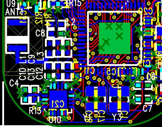
    Here's a close up of the pcb layout. You can see the antenna to the left and the processor to the right and the CC2500 at the bottom.

    Thanks,

    David