This thread has been locked.

If you have a related question, please click the "Ask a related question" button in the top right corner. The newly created question will be automatically linked to this question.

TAS5631PHD2EVM output noise issue

Other Parts Discussed in Thread: TAS5518, TAS5630, TAS5631, TAS3308, TAS5613A

Hi Guys,

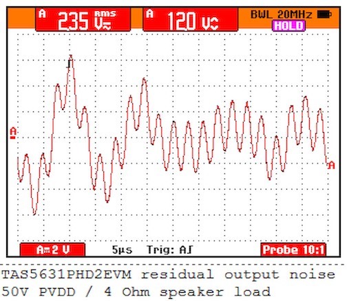
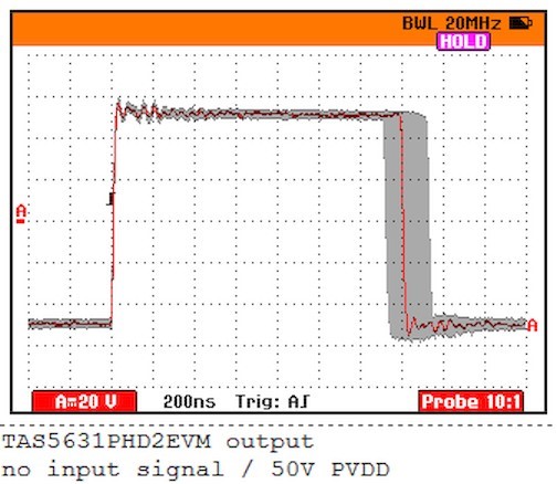
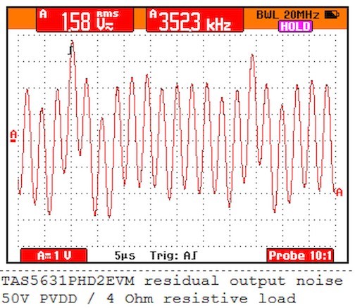
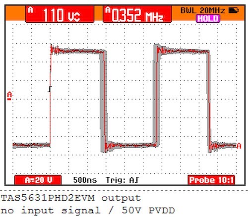
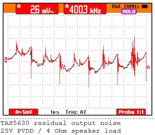
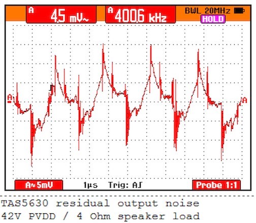
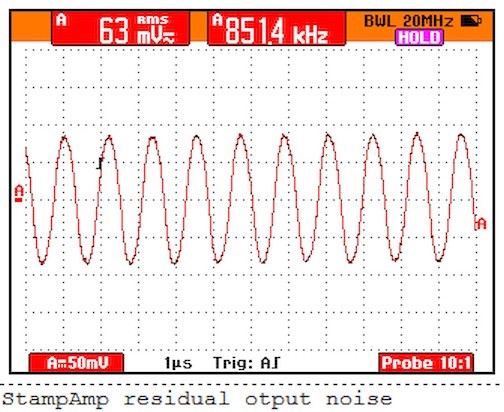
I have significant output noise issue with TAS5631PHD2EVM. First of all I modified the TAS5518 register 0x04 with the value 0x60 to have the TAS5518 automatic mute function disabled. With this configuration I measured what is on TAS5631PHD2EVM output with no input signal and I am really shocked. This is what I measured:


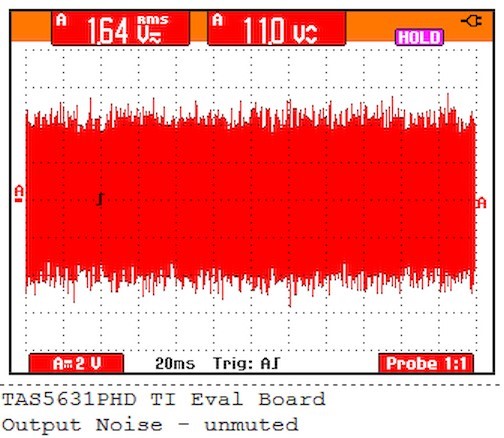
I performed also A-waighted RMS noise measurement in 20k audio band using NTi XL2 Audio Analyzer and got the result around 24mV! First of all I ask me what do I'm measured wrongly??? Why my EVM generate so high noise on the output???

TI declares output noise voltage < 200µV. I do not hear significant higher noise having a speaker connected to the output but I guess it is because of the noise frequency.

Could someone from TI help me to solve the issue please...

Best regards,
Tomasz

  • Tomasz, I think there is a lot of noise outside the audio band in your scope graphs.  A couple of the repetitive features appear to have periods corresponding to about 71 and 51 kHz.

    Do your measurements limit the bandwidth to 20kHz?  If not they are including frequencies that should be eliminated.

    Regards,

    Steve.

  • Hi Steve,

    You are right - there is a lot of noise outside of the audio band in the signal I measured... but I can measure them on the output of EVB - after the filter... I do the measurements with FLUKE scopemeter without the bandwidth limitation. I performed similar measurements on my TAS5630 module, with this same scopemeter / this same configuration, and I never seen such a noise. I've performed similar measurements with NTi XL2 on other Class-D amplifiers and I've never seen such a result...

    Doing a project with TAS5630 I'm currently evaluating the output noise of different Class-D amplifiers. I performed a lot of noise measurement on TAS5630 and they always were more or less in the TI spec. You can read more about it in my other thread on E2E. So, today I wanted to compare the output noise of TAS5630 with the output noise of TAS5631 - TAS5631 should have better noise performance according to TI spec. At first I used my NTi XL2 and tried to measure the TAS5631 output noise, how I every time done on my TAS5630 module. I was a little bit surprised, than even without input signal, TAS5631 sometimes overdrives input of my XL2 Analyzer??? And the XL2 shows around 24mV RMS output noise??? The XL2 measurement is bandwidth limited A-weighted measurement. This is why I connected my scopemeter and understood why the audio analyzed could be overdriven from time to time - specially with even little additional audio signal added.

    Is it a normal behavior of the TAS5631PHD2EVM?

    I measured the output loaded with 4 Ohm speaker.

    Tomasz

  • I guess the high frequency you can see on the second scope screenshot comes probably from the main modulating switching frequency - around 350kHz? could it be so?

  • Tomasz,

    Is this measured differentially across the outputs? This EVM should be running in BTL mode. Making a single-ended measurement to ground may give you misleading results...

    -d2

  • Don,

    Yes - the measurement is done across the outputs having 4 Ohm resistive load connected. I measured with my FLUKE scopemeter 199C with differential / galvanic isolated inputs and 1:1 high impedance probe. The EVM was only connected to regulated power supply and the original input board. I used TOSLINK as a audio source. The measurement is done having paused my audio source (CD player) and the TAS5518 automatic mute function was switched off (register 0x04 with the value 0x60) to have the modulator activated all the time.

    I really think, I made something wrongly ... because the residual output noise measurement looks really terrible... I will try to do the measurement one more time to be sure I connected everything in right way.

    Tomasz

  • Hi Don,

    Today I've found some time and performed the measurement on my TAS5631PHD2EVM one more time. I even used provided on the TI webside TAS5518 configuration:

    X04 60                    - Automute disabled
    Xd9 00 00 00 48   - 0 dB Master Volume

    The results I've got this time are exactly this same like last time and now I really do not understand the issue... Is the TAS5518+TAS5631 so HF noisy on the output??? Are you using the speaker to filter the noise? Or there is something wrong with my EVM?

    First the similar measurement to the one I made last time:

    The measurement was performed on the output of my EVM with 4R small monitor speaker connected to the EVM output. The interesting thing is, when I connected 4R dummy resistive load the results are slightly different - look here:

    Regards,
    Tomasz

  • Don,

    Like the last time, the measurement is taken across the outputs with FLUKE scopemeter 199C with differential / galvanic isolated inputs and original 10:1 FLUKE probe. The EVM was only connected to linear regulated laboratory power supply (50V/5A) and the original USB input board. I used TOSLINK as a audio source. I tried to measure both channels and the results for both channels were quite similar.

    Tomasz

  • Don,

    I took a look also on the PWM signal before the output filter and I can see, that also with really low audio signal, or even with pure zeros send over TOSLINK, the edges of the PWM signal are really jittered - this is what I can see after the output signal as the voltage noise. Look how does the PWM signal on the output of my EVM before output filter without audio stream like:

    The gray envelope shows the jittered signal range in like 15 seconds measurement time.It clearly explains the voltage noise on the output...

    Could you tell me, is it a normal TAS5631PHD2EVM behavior or there is something wrong with my EVM?

    Tomasz

  • Hi,

    Could anyone explain me the issue ... Is my board defected? Do I measure something wrongly? I do not think so, the chip is so poor ...

    Thanks,
    Tomasz

  • Tomasz, I am traveling this week, but I will try to compare to another EVM early next week after I return.  If I find a cause for what you measure, I will let you know.  If I conclude your EVM may be defective I will arrange to have a replacement sent to you.

    Best regards,

    Steve.

  • Steve,

    OK, thanks for your replay. It would be nice if you check the issue on other EVM. There is no need now to replace my EVM even if there is something wrong with it - the board is not so complex, in worst case I could repair it myself (if it is really broken). Next week and the week after I am on vacation so take your time. After comming back I will try to investigate the issue further.

    I have one additional question - what is the source of the TAS5631 / pure digital amplifier noise? Is the noise generated somewhere in the TAS5631 internally or it is comming from the TAS5518 modulator? I checked different designs based on TAS5518 and every design has different output noise level. Even looking on both TAS5518 reference designs (the 2 and 6 channel EVM), the both moduls have different output noise level...

    Do you know the less noisy configuration using TAS5518? Do you know the best performing (noise/THD) PurePath amplifier? Don wrote once using the TAS5518 I could control the output noise level - do you know how to control it?

    Tomasz

  • I´m working on a 8 channel poweramplifier with TAS5518 and TAS5631 and have exactly this problem. Much noise and jitter in the output waveform.

    The A weighted output (differential in BTL mode) is -40dBV!!!

    Another design which uses TAS3308 and TAS5616 is about 20dB better.

    In datasheet the TAS5518 should be quiete better.

  • Hi Steve,

    I am back from vacation. Did you have a chance to test the TAS5631 EVM? Have you found any root cause of my noise problem? Any news?

    Tomasz

  • Hi Kurt,

    So, we have this same problem... The TAS5518+TAS5631 behavior looks really strange... I didn't started my own layout jet, but in this case I wait until we clarify the problem at least on the TAS5518+TAS5631 EVB. On the other side the ultra high noise is not really audible on the speakers, but from the engineering point of view I can not release the design knowing the issue...

    Let's wait how TI explain the issue...

    Tomasz

  • Hi Guys, any chance to clarify the issue?

    Regards,
    Tomasz

  • Hi, Tomasz,

    Sorry for the delay. Let me get someone to look into this for you.

    -d2

  • Tomasz, I have finally been able to check this.  I apologize for the delay; my travel schedule has been very intense lately.  But it seems the problem must be measurement error caused by higher frequency components in the out of band noise of TAS5631 outputs.  It is necessary to filter those to some degree or they corrupt the reading.

    I measured 170 to 190 uV A-weighted at the outputs of a TAS5631 EVM, with register 0x40 = 0x60, no auto mute.  This is in line with the typical 180uV in the data sheet.  My setup was standard, 50V PVDD, 4ohm loads, digital input off.  I have attached the differential output signal captured with my scope, and it looks similar to what you posted.  I used an AP System Two 2322 to measure the noise, with A-weight filtering, bandwidth 22Hz to 22kHz, balanced XLR inputs, auto ranging.

    But there is a trick: with the EVM outputs plugged directly into the AP inputs, the AP will not provide a measurement (it simply reads zero).  We normally use one of AP's LC filters for class-D measurement to filter OOB noise, but I do not have one of these in my lab.  Instead I added 34kHz RC low pass filters at each input, to reduce the higher slew rate out of band noise components, and then the AP read 190 to 200 uV.  (The RCs were 100ohms series with 47nF shunt to ground.)

    There is some error in my measurement from rolloff in my RC filters, but I think there is also still some residual error from the OOB noise.  (When I increased the RC filter rolloff to 50kHz the AP again read zero output, so I have reduced the OOB noise just enough to get a reading.)  I believe on balance the measurement is reasonably accurate.

    I do not expect you to go out and buy one of AP's LC filters, as they are pricey.  But can you try the RC filters and see if you get a more successful result?  (It is even possible to cascade a pair of RC's to get better OOB attenuation, but be careful with that, and be careful with the component values.  Input resistance of the AP is 100k to ground on each side, so there will be some error if the RC filter resistance in series with the AP input is too large.)

    Best regards,

    Steve.


  • Hi Steve,

    Thanks a lot for your replay.

    At first, your scope screen shot is slightly different to what I measured and it is also one of very interesting behavior I observed. I guess you made your measurement using resistive dummy load instead of the speaker. If you would load the amplifier output with real loudspeaker you should get similar scope readout like my one. Look on the measurement I made. First time I measured the TAS5631 amplifier I used 4 Ohm Nubert NuBox311 Monitor speaker I normally use for audio monitoring working on my desk. The scope readout I get was like that:

    The second time, when I tried to reproduce the measurement, I connected 4R dummy load, like didn't think about the differences. I have got then this result:


    I was really surprised why I can't reproduce the first measurement having this same results??? After some tries I connected back my monitors and the I was really surprised - the output signal of TAS5631 depends of the load connected. With the real speakers connected I've got similar scope readout like at the firs time:


    The difference looks to be significant. It means the TAS5631 output behavior depends on the connected load? Do you know how to explain the issue? What is the root cause of it? When I look on the measurement with real load screen shot I can see not just the base switching frequency but also some lower frequency signals like 4-6 time lower than the switching frequency. Unfortunately I haven't any frequency analyzer being able to measure between 50kHz and 500kHz but I have a feeling there is a lot of high power, uncontrolled noise coming out of TAS5631.

    Tomasz

  • I also tried to look directly on the PWM signal and it shows huge jitter. Look on the scope measurements I made directly on the TAS5631 outputs:


    It would be interesting to made an FFT analyze of the jitter to see what is going on there. I guess the jitter shows this same high frequency signal I can measure after the amplifier low pass output filter.

    Do you know what is causing the HF noise???

    I can just suspect, the HF noise is a product of digital PCM to PWM conversion (Equibit algorithm). I know the Equibit converter works with 8-bit samples and strong high order noise shaping. I guess the noise shaping algorithm used in TAS5518 can produce precise signal in audio band but real garbage in the HF band... It is just my guess - I do know know how the equibit amplifier works in deep even if I am quite familiar with the PCT/DK97/00133 Equibit description.

    Could you explain what is the root cause of the HF noise coming out of the TAS5631 EVM?

  • Steve,

    The issue is definitely not present in analog input class-D amplifiers like TAS5630 and the whole family. I measured in similar way the TAS5630 and other class-D amplifiers output. The TAS5630 output looks like that:

    You can just see the noise produced by switching the PWM.

    I have on my desk also other super simple class-d amplifier which I like very much because of having very quiet output looks like that:


    Next time I will try to measure the TAS5613A I really like. At the moment TAS5613A is my favorite TI amp.

    I would like to investigate the equibit noise performance a little bit deeper but I think I make separate thread for that.

    Tomasz

  • Tomasz, you are correct that noise shaping will produce clean signal in the audio band and artifacts out of band.  Of course, that is its purpose, to push noise into regions where it will be ignored by insensitive transmitters (speakers) and receivers (human hearing).  But I think it is a good trade.

    I think the most important point is that filtering is necessary with almost any analyzer to reduce the impact of the OOB noise elements enough to get a proper measurement.  I hope you're able to try that and succeed with it.

    If you want to know the details of the noise shaping, please place the post on the Audio Converters forum.  Our converter people will be able to answer the question much more quickly than I.

    Regards,

    Steve.