This thread has been locked.

If you have a related question, please click the "Ask a related question" button in the top right corner. The newly created question will be automatically linked to this question.

DRV8811 Schematic and Timing

Other Parts Discussed in Thread: DRV8811, MSP430F249

Hi,

I built a circuit with a DRV8811 and I'm having some trouble with it.  I have a few questions and need some help with the schematic I made.

First, the errors.  My motor is just whining, and not moving, even though I am not sending out anything on the STEP pin.  (I am programming an MSP430F249)  The only way I can get it to stop is to set the ENABLE pin high, which works and kills the outputs.

In the circuit, I have the decay set up for fast decay and I have a 1.6 ohm resistor for Rsense on both coils (should be just over 0.25 A).  I am a little confused on what the resistors and capacitors on RCA and RCB mean.  The datasheet says it sets the off time in the pulse.  Does this mean that this is my PWM being set by these? Do I still need a PWM on the step pin?  If these do not set the PWM, than what does the off time mean? How does that relate the the timing of the PWM signal sent to the step pin?  I am currently using a 1000pF cap and another 1.6 ohm resistor to set these.  (I think that is somewhere between 1 and 2 ms).  Is that correct? I want my PWM to send a 1 ms (ish) pulse as that is a good speed for my motor.

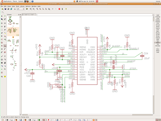
I am still a little confused as to why my motor whines without anything on the step pin.  Could someone glance at my schematic and see if there are any obvious problems?  The enable obviously works so I'm assuming I did something else wrong.

Thanks much.

  • Hi Connie,

    I am happy to report your system is working as expected. I do agree you may not be pleased with the noise problem, but at least I can tell you this is normal with steppers. We have documented quite a bit different techniques on how to solve the problem, so feel free to browse any one of my postings on the DRV8811 and I am positive you will find the answer you are looking for. As a quick summary do let me suggest either slow decay or mixed decay, and try to use only as much current as really needed. If the motor is not moving, just place it in slow decay and decrease the current to a value in which you can still hold your torque. Do note that it is basically impossible to make the stepper 100% silent if using a current chopper topology (in open loop configuration, that is). There will always be an audible component and all we can do is minimize it as much as possible.

    With regards to your other questions on te RC components, I suggest you take a look at the datasheet where there are some diagrams that show how the current regulation works. This is hard to describe with a few sentences but as a summary:

    The C deals with the TBLANK (1400*C in us if I recall)

    the RC will tell you what is the TIME OFF (R*C in us if I recall)

    and the TIME ON is given by the motor inductance, power supply voltage and motor speed (e.g. BACK EMF).

    Frequency will be 1/(TON + TOFF) so each system is unique. You may need to tweak the RC values to obtain the desired frequency and anything in between 20 KHz and 32 KHz should work nicely. Anything less than 20 KHz will haunt your ears, and anything above 32 KHz will increase switching losses more than necessary.

    Hope the info helps. Best regards,

    Jose Quinones