This thread has been locked.

If you have a related question, please click the "Ask a related question" button in the top right corner. The newly created question will be automatically linked to this question.

Lipo Cell Read with ADS7953 and analog multiplexer

Other Parts Discussed in Thread: ADS7953, INA2132, INA149

Hello, sorry for my English

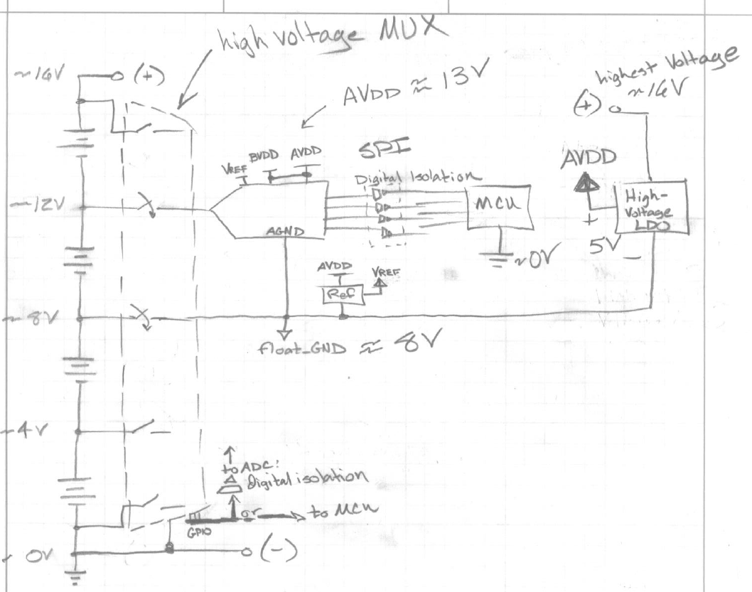
I want to realize  a board for reading a few lipo battery's. But to read the correct potential of a cell, I have to connect the negative terminal of each cell to AGND. Therefore I want to use a 16channel analog multiplexer with 4 select pins and I want to connect the 4 select pins to the GPIO's of the ADS7953 and the output to AGND. With this combination, I could use the ADS7953 in manual mode and I chance the GPIO's to chance the multiplexer and the AGND potential. Then I could read the correct cell potential.

Is my plan possible with the ADS7953 and a microcontroller?

Which 16channel analog multiplexer could I use?

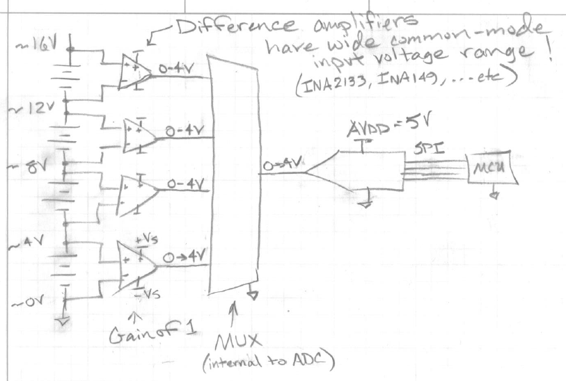
Or are there any other opportunities to get the correct cell potential from the balancer output?

Greetings

Philipp

  • Hi Phillip,

    Welcome to our forum!  Your English is fine!  Could you possibly provide a schematic showing the cell voltage(s) you are trying to sample?  Is this a series stack or a combination of series/parallel batteries?

  • Hello and thank you ;)

    Lipo battery's have got an balancer plug. ("to charger" in the image). The volatage of each cell can be from 4,2V to 3V. When I want to read the voltage of each single cell, I have to connect the negative terminal to AGND of the A/D, and the positive terminal to the A/D input. But therefore I need to switch between different negative terminals, and I want to realize it with a analog switch/multiplexer. Is this possible?

    Greetings

    Philipp

  • Hi Philipp,

    Will the batteries be disconnected from the circuit when you measure the cell voltage of each or are you trying to measure the voltage in-circuit?

    • Measuring each cell while disconnected will require more switching but will simplify the connection to the ADC.
    • If you measure the voltage in the circuit you will have to deal with large common-mode voltages and you will not be able to connect directly to the ADC without damaging the ADC. In this case, one solution would be to use a differential amplifier, which can handle the large common-mode voltages because they are reduced by resistor dividers in the differential amplifier network.

    Regards,

    Chris

  • Hi,

    thank you so far. I want to read all cells in-circuit with about 10Hz.

    What would be, when I use 2 Analog Multiplexers. When I want to connect a cell to the ADC, I first would disable the outputs of both multiplexers, then I could conect the negative terminal of the cell to AGND and then I would connect the positiv terminal with the multiplexer to the ADC input. After I read the voltage, I would disable both multiplexers again, and then the same again. Theoretically when I do this, there should only be a potential of 3-4,2V on the ADC.

    The ADS7359 also has got multiplexed ADC pins.

    Could I something in this direction?

    Greetings

    Philipp

    P.s. I found delta-sigma on the internet with a vin- and vin+ connection. Could I also multiplex the cell terminals to that pins?

  • Hi Philipp,

    I drew the following picture below to illustrate my understanding of your application. Drawing it out also really helps you see how all the elements are referenced to one another.

    Notice the relative and absolute voltages in the circuit. If we treat (-) as the absolute ground (0 V) then we see voltages up to ~16V in the circuit. You're treatment of the ADC is okay because you are creating a "floating ground" that will change so that the ADC input voltage is <5V. However, there are many other elements in the circuit which are still in danger.

    1) The MUX/switches are always connected to the battery stack, even if they are not connected to the ADC. This means the the MUX(s) will need to be able to tolerate the high voltages...you can do this but you may find that these devices have high on-resistances and therefore noisy.

    2) The digital connections from the ADC will need to be isolated so that the MCU is not subjected to high voltages. This gets a little messy...

    In my humble opinion - I think a better solution may be the following using difference amplifiers:

    1) The diference amplifiers can front the large input common-mode voltages and no isolation is needed.

    2) The internal ADC multiplexer can now be used and the switching scheme is much simpler.

    I would strongly reccomend the later circuit over the first. The first would be do-able but has many oportunities for something to go wrong.

    What supplies do you have available to you to power the difference amplifiers and how much offset voltage voltage can you tolerate? Also, what resolution & accuracy do you need for your voltage readings? These will help determine which components to use for the difference amplifiers and ADC.

    Best regards,

    Chris

  • Hi,

    I think the difference amplifiers would be the best solution.

    The hole circuit should be as small as possible. I need about 16 channels adc. But two channels are used to read from a shunt, but I have already a solution for that. (ACS758ECB-200U output range 0-5V). We use LipoBatterys from 2 (8,4V) to 8 (33,6V) cells. One cell's voltage is from 3V to 4,2V. It would be fine if there is a fitting ic with about 4 or more differential amplifiers.

    I have also found a SPI Optocoupler solution (ACPL-064L andACPL-M61L). The operating Voltage of the differential amplifiers and adc should be 5V.

    Greetings Philipp

  • Hi again Philipp,

    To help you save space, If you're using the difference amplifier solution you should be able to get by without the optocouplers. For the difference amplifiers I would recommend the INA2132 or the INA149.

    The INA2132 is a dual difference amplifier so you would get two difference amplifiers in one package. The downside to the INA2132 would be that it's input common-mode voltage is lower than the INA149. If you wanted to use four INA2132s to connect to all eight batteries in a stack then you would need to play with the supply voltage that you use to power all of the INA2132s to be allowed to connect to the 7th and 8th batteries in the stack where common-mode voltages are reaching ~28V and ~32V. You would need to test using an odd supply range such as +20/-10V supplies (Something higher than +15V and slightly negative to measure what you want). You would have much more flexibility with allowable supply voltages and input common-mode ranges with the INA149 but you would need eight of them.

    Which ever difference amplifier you decide to use, I would plan how you plan to power them first. You should be fine using the ADS7953 16-channel ADC.

    Regards,

    Chris

  • Hi, i need to help. I''ll use to ina2132 differantial opamp for measuring to battery voltage. My max Vin voltage is approximately  55v. How much voltage should i to vs? 15v was used to reap bms.