This thread has been locked.

If you have a related question, please click the "Ask a related question" button in the top right corner. The newly created question will be automatically linked to this question.

Proper command sequence for ADS8332 multichannel operation

Other Parts Discussed in Thread: ADS8332

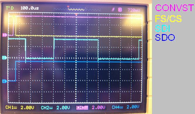
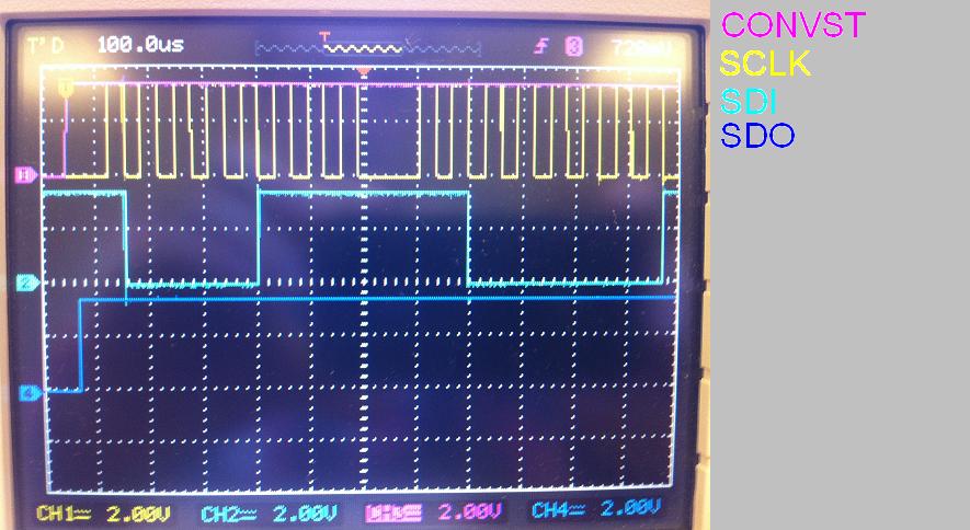
Hi,  I am using MCBSP-SPI( of DSP TMS320C6713) to communicate with ADS8332, and I am successfully able to communicate with ADC for the single channel in Manual Mode  - Auto Trigger mode, I am sending the ADCs with following commands

  1)0xE4FD( SDI) --> Write CFR

 2)0xC000 ( SDI)--> Read CFR and i got 0xF4FD on SDO

  3)0x0000( SDI)->READ DATA and i got data on SDO ( for channel 0)

  4) Go to step 3

now if i want read 2 channels i ll be sending

 1)0xE4FD( SDI) --> Write CFR  

2)0xC000 ( SDI)--> Read CFR and i got 0xF4FD on SDO

  3)0x0000( SDI)->READ DATA and i got data on SDO

  4)0x1000( SDI)->READ DATA and i got data on SDO  

 5) Go to step 3.

 but when I plot the data I am recievng from the steps 3 and 4, it gives me the signal of One of the channels and not the 2 channels,

I want to know whether I am send the commands properly, if not please provide me the proper sequence for

  1)ADC to operate in Multichannel  mode, Manual mode, auto trigger mode and

  2)ADC to operate in Multichannel  mode, Auto mode, auto trigger mode.

 If anyone has any idea with the working ADS8332 and tapped the O/Ps,  please guide me.

Thank you,

Deepa

  • Good day Sir,

    as I was looking for information about how to get the digital ADC ADC8331 running I found this thread. I cannot establish a communication with a single chip and hope to find support here. I am not sure if I connected the chip wrong, or if I made an error when initiating the configuration register. I would start explaining how I connected the chip. The following list describes how I understood to connect the 24 pins:

    1) IN1: 1V DC test signal which cannot be observed on the SDO-channel
    2) IN2: NC
    3) IN3: NC
    4) NC
    5) NC
    6) NC
    7) NC
    8) Reset: NC
    9) EOC/INT/CDI: Not connected since I do not wish to evaluate this information. Is it correct that I do not use this pin? As I understood it the EOC-pin is only for evaluating whether or not the conversion is complete in the microcontroller.
    10) SCLK: Master clock from uPC
    11) FS/CS: Channel Select from uPC
    12) SDI: Master output from uPC
    13) SDO: Master input from uPC
    14) DGND: Connected to AGND
    15) CONVST: Connected to output from uPC
    16) VBD: Connected to VA = 3,5V
    17) VA: 3,5V
    18) REF+: Connected to VA = 3,5V
    19) Ref-: Connected to AGND
    20) AGND: Ground power supply
    21) ADCIN: Connected to MUSOUT
    22) MUXOUT: Connected to ADCIN
    23) COM: Connected to AGND
    24) IN4: Test signal AGND

    In the following I explain how I initiated the configuration register according to the data sheet on page 28. LSB first:

    0) System reset to '1' automatically
    1) TAG bit disabled
    2) Deep Power-Down disabled
    3) Nap Power-Down disabled
    4) Auto-Nap Power Down mode disabled
    5) Pin 10 is used as EOC/INT output
    6) Pin used as EOC
    7) EOC/INT active high
    8) 500kSPS
    9) Auto-Trigger: If I use this mode do I still need the CONVST-pin?
    10) Conversion clock (CCLK) = SCLK/2
    11) Auto channel select enabled 

    I cannot send you pictures, but clock-channel, CS-channel, CONVST-channel and SDI-channel show what I expeted to see on them. The CONVST high signal arrives before the CS low signal. Then I observe the CFR bytes cycling through with each clock cycle. Still I cannot observe any communication on the SDO-channel even though different test signals are applied to channel 0-3. The SDO-channel goes high when the CS-channel goes low, if that helps narrowing down the error. I would be very grateful for any support and tipps you can give me in order to get the chip running.

    Best regards,

    Jan

  • A small update concering the question above. I uploaded two pictures of the signals that can be observed when trying to communicate with the ADC8331. I loaded in this case a 0000b into the CMR. Since I configured the auto-trigger mode in the CFR do I have to upload a 1101b into the CMR for reading data, or maybe a 1111b for default mode? I hope the pictures help too. I gladly deliver more inforamtion if needed.

    Best regards,

    Jan