Because of the holidays, TI E2E™ design support forum responses will be delayed from Dec. 25 through Jan. 2. Thank you for your patience.

This thread has been locked.

If you have a related question, please click the "Ask a related question" button in the top right corner. The newly created question will be automatically linked to this question.

On Reference/Bias electrode of ADS1299 EEG-FE

Other Parts Discussed in Thread: ADS1299
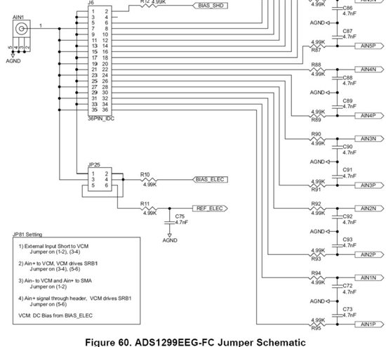
In regard of the ADS1299 EEG-FE, I have checked the diagrams on page 51-2 of the "ADS1299EEG-FE user guide" and still have doubts on how to connect the reference electrode and bias electrode.  
 
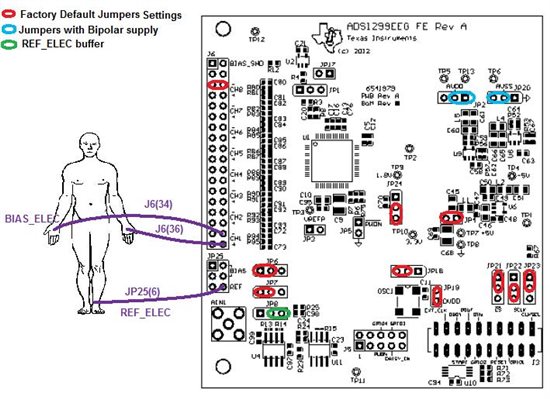
(1) If I have 3 electrodes from right frontal, left frontal and earlobe respectively, which pins of the J6 and JP25 should I connect these 3 electrodes to? 
(2) Is the AIN1 pin 1 used as the reference electrode input?
(3) If the jumpers on J6 and JP25 are set as factory default except pin 35-36 on J6, where I connect a single-ended sine wave to pin 36 and connect pin 35 (also connected to AIN1 pin 1) to ground,  is the BIAS_ELEC input the one that I can use to connect to a reference electrode? From the diagram, I see the BIAS_ELEC input is connected to the REF_ELEC through R10.
Thank you so much for your help.
  • Hi Xinling,

    Thanks for your questions. While we are not experts in EEG, I think I can provide some guidance here:

    1. Typically, your frontal electrodes would both be referenced with respect to a common reference point on the body. I'm assuming this is the intention of the earlobe electrode, correct? There are two options for routing the reference:
      1. Use the appropriate pins on J6 to route the reference to AINxN.
      2. Use REF_ELEC and route the reference through SRB1, which connects to all AINxN inputs internally. This option allows you to buffer the reference through U4, if desired.
    2. AIN1 was not intended for the reference electrode. It is just another way to input signals to the positive channels inputs.
    3. The BIAS_ELEC is an output from the ADS1299 that is intended to set the common-mode point of the patient. This also helps to improve common-mode rejection in your measurements. This is very similar to the Right Leg Drive technique used in ECG applications.

    Does this help clarify the EVM connections?

    Regards,

  • Hi, Ryan,

    Thanks for your guidance. I really appreciate your help.

    Yes, the earlobe electrode is intended to be the reference electrode, I am sorry for not clarifying it before. Now I think I understand the reference electrode connection.

    a.  If I connect left/right frontal electrode to pin 36/32 of J6 respectively, I can connect the earlobe electrode to pin 35/31/AIN1, is that right? (jumpers the other channels and 33-34 and 29-30 are connected, and SRB1 bit not set)    

    b. Do you mean I can directly connect the reference electrode on pin6 of JP25 and set the SRB1 bit in MISC1 register without connecting pin 33-34 and 29-30 in J6 because those pins 34 and 30 are already connected to SRB1? How should I set those pins on JP25? 

    In regard of the Bias electrode, I understand it is like the Right Leg Drive circuit in ECG recording.   Should I use pin 4 to connect the bias electrode out? How should I set other pins in JP25?

    I am so confused by the “JP81(25) Setting” in the diagram. Thank you so much for helping out.  

  • Hi Xinling

    I have the same doubts as you ....
    How you solved it? I have the following figure, but doesnt work...  in the software I didnt change anything.
    I'm looking for Section 7....to triying

    Norma

  • Hi,

    Did you find out to which pin Bias_Elec should be connected to?

  • Hi Carolina,

    The BIAS_ELEC can come from one of two sources: BIASOUT, which is the output of the internal bias amplifier, or an external buffered mid-supply voltage. BIASOUT is connected to JP1[2]. The external, buffered mid-supply is available on JP6[2]. Choose which source you would like to use for BIAS_ELEC and set the respective jumper to the [1-2] position, leaving the other one uninstalled.

    The BIAS_ELEC voltage is available on pins 2, 4, and 5 of JP25. From here you can connect it to several places, such as an external patient bias electrode, the negative channel inputs on J6, or the REF_ELEC node, which is routed back to the SRB1 pin on the ADS1299.

    The source of BIAS_ELEC and what is it used for depends on the application criteria. Primarily, it is used to generate a mid-supply dc common-mode voltage to bias the body relative the ADC system. In addition, it can also carry an inverted ac common-mode signal that cancels the common-mode noise on the body to improve system CMRR. This can be done inside the ADS1299 by configuring the BIAS_REFINT and BIAS_SENSx[7:0] bits in the device register settings.

    Best Regards,
  • Thank you Ryan!

    Just to clarify...

    If I decide to use BIASOUT as the source for BIAS_ELEC I would leave JP6 uninstalled and place a jumper on JP1 [1-2]. For the software in CONFIG3, is there something specific I need to select?

    If I decide to use an external buffered mid-supply voltage, I would leave JP1 uninstalled and place a jumper on JP6 [1-2]. Then in the software for CONFIG3, I would enable the BIAS Buffer and leave BIAS Measurement open?