This thread has been locked.

If you have a related question, please click the "Ask a related question" button in the top right corner. The newly created question will be automatically linked to this question.

ADS1248 How to read the temperature

Other Parts Discussed in Thread: ADS1248

Hallo,

I am working with the ASD1248 and have connected three detector RTD (Pt100) .

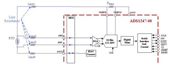
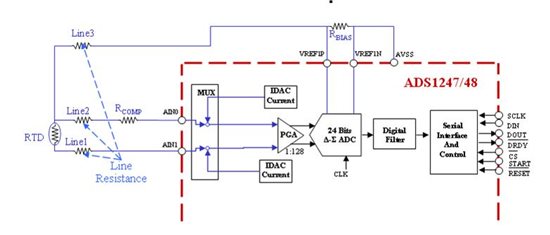
first Pt100 :  Connected from AINo to AIN1  and AIN1  is connected to REFP0.     Figure 82(Datasheet) 

second Pt100 : connected from Ain2 to AiN3 and AIN3 connected to REFP0.

third Pt100 : connected from Ain4 to AiN5 and AIN5 connected to REFP0.

How should i write the programme to read the temperature of those PT100.


Thanks:

  • Hi Baho Florian, 

    There are two ways you can approach configuring your ADS1248 for your RTD application. 

    First way - Dedicate one of the analog input channels as the IDAC current source. Then you can run the current source through all the RTD resistors and through the Rbias resistor which sets your reference voltage. Similar to the 4 wire RTD implementation that I have attached to this post. Then go through and cycle the internal mux to convert the differential voltage across each of the pt100s.

    Second way - Go through and enable the IDAC current source for the channel you are converting. Then disable the current source, change the mux to the next differential channel pair, enable the corresponding current source and convert.  This is more similar to a 3 wire RTD implementation. 

    Regards,

    Tony Calabria

  • Hi Tony,


    In the secnd method shown above, if I have more than 1 3-wire RTD, then:

    1) Can I connect all the RTDs to the reference voltage via RBIAS?

    2) If yes, then I need to access each of the RTD once at time rght?

    3) While accessing each RTD, won't there be a drop for the remaining RTDs and it won't make any error in my readings?


    Thanx,

    Himanshu.V.Ajmera

  • Himanshu,

    Yes, it is possible to connect more than one 3-wire RTD to the ADS1248.  It is possible to have 4 separate RTDs to dedicated input channels as there is an eight channel mux.  In the case mentioned, connect each RTD Line3 to the RBIAS resistor.  As there is only one converter in the ADS1248, you will need to select one set of inputs at a time, and set the IDACs accordingly as each RTD is measured.  Unused inputs are switched off within the mux and do not provide a current path.

    One other alternative with the ADS1248 is using two RBIAS resistors as there are two external reference inputs.  Using this method you can have two totally independent RTD measurement systems.  This can be a benefit when using two different ohmic value RTDs where the RBIAS resistors would need to be different values as well.

    Best regards,

    Bob B

  • Hi Tony,

    Thanx for the reply, I forgot to mention that I will be using ADS 1148 instead of ADS 1248 and I guess that won't make any difference to my circuit as 1148 is 16-bits and 1248 is 24-bits.

    Thanx,

    Himanshu.V.Ajmera

  • Hi Bob,

    As per your reply, I have made a schematic. Can you verify that it is correct? I want to be sure before I can actually start PCB designing.

    One more doubt i have is, why do we need to provide both the current source to a 3 wire RTD i.e. why both IDAC1 and IDAC2 are connected to the RTD and if possible can you explain the working? Isn't one source enough to excite the sensor?

  • Himanshu,

    Your schematic is basically correct.  You may want to review this application note that is specifically related to temperature measurement using RTDs and the ADS124x family of devices (which also applies to the ADS114x devices.)

    http://www.ti.com/litv/pdf/sbaa180

    Is it possible to use a single current source?  Yes, you could do so but you will introduce errors from a voltage drop across the line resistance of the RTD from the current flowing through it.  Using two current sources provide symmetry and the line resistances will cancel each other.  Is R1-R8 actual resistors or are you using these values to show line resistances of the RTD?  This is the only thing I'm not sure about in your schematic, and why I said it is basically correct.

    Review the application note and try to further your understanding on how the circuit works and why it is a good idea to use both current sources.

    Best regards,

    Bob B

  • Bob,

    First of all thanx Bob for the reply. Yes, R1-R8 are the line resistance.  I went through the application note and I am bit curious as why only 1 current source is used for 2 wire or 4 wire RTD? I know its not related to my application anyways but its better to have some extra knowledge. And one more thing, do we neeed to take the readings from all the RTD twice or only once is?

    Regards,

    Himanshu.V.Ajmera

  • Himanshu,

    For the 2 wire and 4 wire RTD case, there is no advantage for using both current sources.  For the 2 wire case, the current will not drive in both directions through the RTD, so the additional current noise through the RBIAS resistor will differ from the the current through the RTD and the ratiometric system will no longer exist.  For the 4 wire case, the current does not flow through the inputs, but rather where a single path is created through the RTD which is measured across high impedance inputs.  This means the line resistance to the inputs can be neglected, and the voltage drops in the line resistance within the current path can be ignored as they have no impact on the measurement.

    I would suggest that you look again at the diagrams in the application note and add current sources at various points and do a loop analysis of the current paths.  I think that once you do this you will see more conclusively why the specific current paths were chosen in each design.

    Best regards,

    Bob B

  • Bob,

    Thanx. Certainly, I will do the analysis for each RTD. I had read somewhere that we have to take 2 readings from each RTD i.e. 1st time by connecting the current source as it is for example IDAC1 to AIN0 and IDAC2 to AIN1 and 2nd time by swapping the current source example IDAC1 to AIN1 and IDAC2 to AIN0-is this true?

    Thanx,

    Himanshu.V.Ajmera

  • Himanshu,

    For the three wire RTD, if the current sources are not well matched, then you may want to swap the current sources and repeat the measurement to see the difference in the two measurements and compensate appropriately.  However, as the ADS1248 IDACs are well matched and derived from the same reference, this should not be necessary. 

    Ultimately the decison is yours as to whether you need to swap IDACs and take multiple readings.  You need to take system measurements over temperature and verify that whatever method you choose satisfies your design requirements. 

    Best regards,

    Bob B

  • Bob,

    Thanx for all the reply.

    Regards,

    Himanshu.V.Ajmera