This thread has been locked.

If you have a related question, please click the "Ask a related question" button in the top right corner. The newly created question will be automatically linked to this question.

How to solve the "video noise" with the TVP7002?

Other Parts Discussed in Thread: TVP7002

Hello,We use TVP7002 to capture HD PC graphcs video from NoteBook or other video sources.

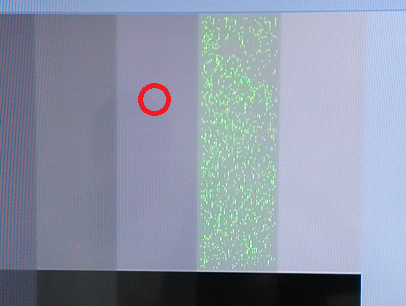
Now,the video we get has some video noises.It is a "lighting point" with RED or GREEN color.

What may cause this LIGHTING POINT?How to solve it?

Expecting for any reply.

Thanks in advance.

  • This type of artifact is most often caused by either sampling phase errors (i.e. the analog video is being sampled close to a rapid change in the analog video) or a timing violation between the digital outputs of the TVP and the target for the digital video (i.e. there is a setup/hold violation in the digital domain)

    Having said this though, both these root causes only show up when there is a transition, so if the analog video is, for example, a solid gray color then there ARE no rapid level transitions in the analog waveform hence sampling phase is not the cause. Likewise in the digital domain if the TVP output is RGB 444 and the source video is a solid, stable color, then again there will be no transitions on the digital output signals, hence no setup/hold violations since there are no transitions (not in the middle of the display as shown above anyhow).

    How are you subsequently processing the output from the TVP7002? Is it possible that this subsequent processing is introducing the artifact?

    What is the output format of the TVP7002? (i.e. RGB444, YUV422 etc...)

    What is the actual source image? (In the picture it looks to be flat gray, but if it is actually alternating black/white, for example, then it could be either of the above mentioned possibilities)

    Try changing the sampling phase.

    BR,

    Steve

  • Thanks for your detail reply.

    Today I tested again,the notebook computer outputs a color bar via vga to TVP7002.During the "solid and flat color" region,there are some "lighting points",altough not many.

    TVP7002 outputs YUV 4:2:2.

    I think,even if the video is a solid clor bar,the VGA is a analog signal,so it is still possile for TVP7002 to capture a two digital different rgb data during two "same" pixels,because a Analog to Digital conversion can bring noise or something else.

    You mentioned that I can adjust the sampling phase.

    In the register "HPLL phase select" .There is a mention "a host based automatic phase control algorithm can be used to optimize..."

    What's the phase control algorithm?

    How to set this register?

  • If there are sparkles in the flat color region and the TVP7002 is configured for 422 output then the most likely cause is a timing issue between the TVP and the target for the digital data.

    You are correct that a solid color will still have 'noise' but since this is entirely internal to the TVP it is not possible for this to be a timing error and any slight variations in the video level will be correctly captured and processed. Using 422 output means that the digital chroma outputs are rapidly changing hence more likely to show external timing issues.

    Are the sparkles always in the same place or do they jump around?

    For the sampling phase there are many, many different ways to determine the best phase, but basically it involves sweeping the phase from one extreme to another, then looking at the captured data on edge pixels to see where the transition occurs (i.e. where the black to active image data is found) on each of left and right edges then set the phase to the mid point. The exact details of this algorithm will be part of your company's IP. All monitors capable of receiving analog VGA have their own way of doing this and it is not a simple task to do efficiently and accurately, especially for very high resolutions. All monitors have either a button or a menu option called something like "auto-set", "auto", "auto-align" etc... Try this on some monitors to see what/how they do this from a high level.

    BR,

    Steve

  • First,Its mode is 720P60,so I think it's not a big problem for timing issue.I used a constrained track to match length in pcb deisgn.

    It's clock rate is just 74.25M max.

    Second,It seems the sparkles are in some fixed locations,but sometimes it "LIGHTs",sometimes it is normal.

    just now I tested again,useing a notebooke computer to display a gray bar to TVP7002 via VGA.

    720P60 mode.

    The picture source is following:

    And the display picture is:

    there are lots of GREEN POINTS.After a while,the GREEN POINTS desappear.

    I am very confused about this.

  • This is most likely a timing issue between the TVP7002 output and the next device.

    This looks like a classic setup/hold violation on the input to the next device in the chain.

    Try changing the output clock polarity with the CLK_POL control bit in register 0x18.

    BR,

    Steve

  • Thanks very much!

    It solved!

    The main cause is not "timing issue",It's that I didn't understand the setup time,slack,so deeply.

    Thank you again!

  • Excellent. Glad you are working correctly now :)

    BR,

    Steve