This thread has been locked.

If you have a related question, please click the "Ask a related question" button in the top right corner. The newly created question will be automatically linked to this question.

RGB frequency of LightCrafter 3000

Other Parts Discussed in Thread: DLPC300

Hi,

I measured the RGB light frequency and found out that:

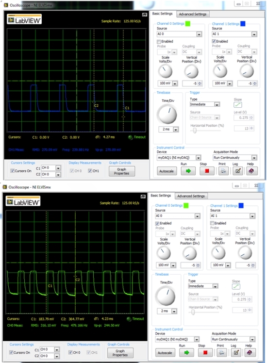
1)  RGB light source has period of about 4.27ms (+/-240Hz)

2) The Blue LED has one pulse and Read and Greed have two pulses per period

According to the "DLPC300 programmer's guide" the frame rate should be 60Hz, it means that for each frame there are four sequences of RGB impulses with total 4 impulses of Blue LED and 8 impulses for Green and Red LEDs. 

I would like to know why the LEDs turned on and off more times per period? To me it seems more logical to turn them on only once per period. On figure below the Blue LED (blue curve) and Green LED (green curve) activity is shown. 

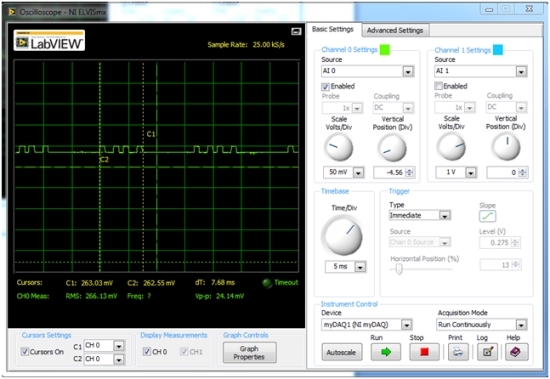
Another interesting thing is that when static image of video is loaded to DMD the LEDs are active only for a half of the period and the second half of the period they are either in off or on state. On the picture below green static image was loaded to the DMD and reflected light activity was measured. As it can be seen for half of the period all mirrors/LEDs are off. Why would you need to keep LEDs/mirrors of for half of time?    

Thank you everybody how can shed light on my questions.

Alexey 

  • just curious if you have found any answer... i'm interested as well.

    Also, where can I find DLPC300 LED interface timing diagrams? It's not in the DLPC300 datasheet.
  • Hello Alexey,

    Please provide the information on the Modes you are operating, from your description i am assuming you are attempting a) Static Display Mode b) HDMI Video Mode (driving external video source), correct me if it is wrong.

    The DLPC300 in these modes, run what is called as Normal Video sequences, these display sequences, this is described in Programmer's Guide Table 2-80. DLPC300 16-, 18-, and 24-bit RGB External Video Sequences, note here, they have allocated different % of time for displaying data for each channel, 35% - Red, 45% Green, 20% Blue. The sequences are designed for producing good image for viewing by human eyes. So if we were to follow the Figure 2-7, for displaying, it will create what is called as "PWM Artifact", to reduce such a thing, the incoming RGB 888 pixel data is shown multiple times and in the specified dutycyle % (display time) for the channel.

    Note, the video sequences are designed for specific LEDs, LED driver on/off timing characteristics, (in this case for whatever hardware used on the Kit), if you replace the LEDs or the LED driver it may not produce good image.

    Now there are other modes, Pixel Accurate mode, where it will not do so (uneven repeating showing odd pulses between Red Green and Blue), as explained in 2.3.1.1.2 Pixel Accurate External Video Sequences.

    Regards,
    Sanjeev
  • About LED interfacing diagram -

    You can refer to LED driver schematics (sheet #5) , in principle b/w LEDs and the DLPC300 controller there will be LED driver circuit (shown in Sheet #5 of the LED Driver schematics), the LED driver circuit accepts total 6 signals from the controller,

    First three for ON/OFF control
    LED_RED_EN
    LED_GRN_EN
    LED_BLU_EN

    Second three for LED Current control - the signal is basic PWM signal with DutyCycle as as function of current strength to applied to the LEDs.
    RED_PWM
    GRN_PWM
    BLU_PWM

    Regards,
    Sanjeev