This thread has been locked.

If you have a related question, please click the "Ask a related question" button in the top right corner. The newly created question will be automatically linked to this question.

ADC error

Other Parts Discussed in Thread: CC2510

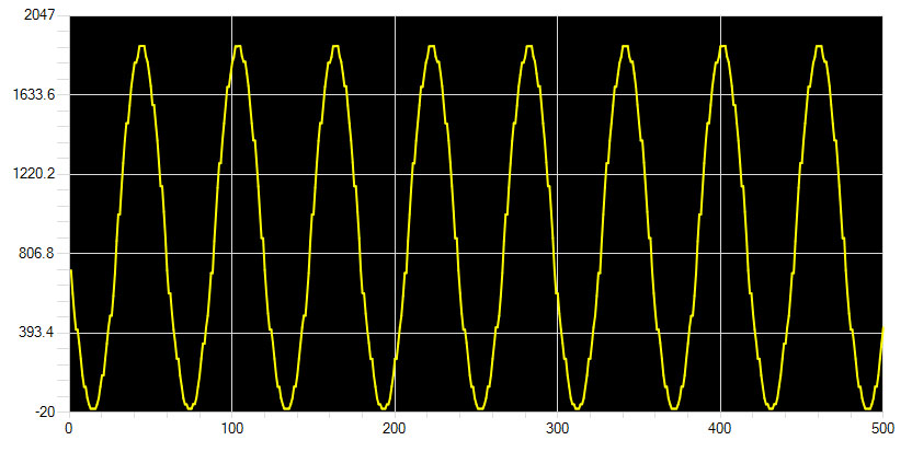
Please see the picture below,


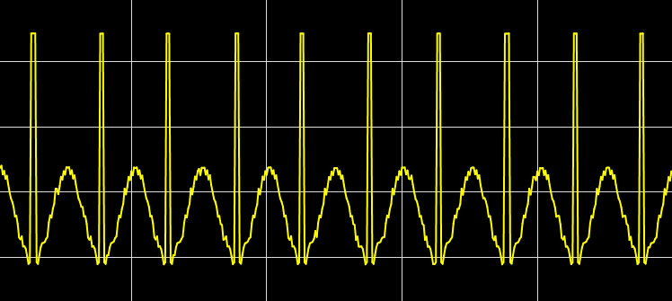
I am converting a sine wave, the lowest voltage get "clipped off" and returned the highest possible ADC conversion number.

I am new in this field, is this a well known phenomenon that ADC tends to mistake the "close to 0V" as the "VREF" and return the highest possible number (for 12 bit, 4095)?  And how to deal with this?

Thanks!

  • Indeed, if I set any pin (for example, p0) as a single end input, and then use a wire to connect the ground pin to the p0, the ADC will return the highest possible number.  And if I set any two pins as the differential input, and then use a wire to connect these two pins, the ADC will return the highest possible number as well.

    This is done on the cc2510 mini development kit.  Really weird, why is that?   

  • Hello Lei Chen1,

    As the responder to your previous post noted, the ADC data is a signed value which you need to convert using Two's complement.  You may want to consult a digital textbook or even wikipedia for some basic two's complement information if you need it.   The MSB of a signed value indicates whether it is negative or positive (0=positive, 1=negative).

    You note the value is 4095, which tells me you are treating the number as an unsigned value, however when treated as a signed number a value of all ones (1111 1111 1111) is equivalent to -1, so the value you are getting is actually correct.  

    Regards,

    BK

  • Hi, BugKing,

    Thanks for the reply!  And thank you for pointing out the error (ie, I treated a signed number as a unsigned number), which does explained it.

    I understand that the MSB is the sign bit, but I still don't know how to send a signed ADC data over the radio.

    So for example, if I write the following,

    int8 ADCH;

    SMPL_Send (linkID, &ADCH, 1);

    The IAR will give me an error saying that the int8 does not match the type of data that the radio send, which is unit8.  In another word, no matter how you format it, the negative number is a negative number, and if the radio can only send a positive number, how does it work?

    Thanks!

  • I tried to cast the ADCH before sending it over the radio, using the following code,

    uint8_t uADCH = (uint8_t) ADCH;

    SMPL_Send (linkID, &uADCH, 1);

    But did not seem to work.

  • Solved the problem finally,

    Quite simple actually, just add a sentence, "if adc<0, adc=0", so that "-1" will not be mistaken as the "111111111111".

    The sine wave I am sampling actually goes from 0V to 3V (well, at least that's what the function generator is supposed to do), so the ADC result should never goes below zero, although BugKing precisely pointed out the problem, I still do know why ADC went below zero.

    Well, quite a learning experience, and thanks everyone, now I have to figure out how to increase the sampling rate so that the sine wave will look smooth.

  • Try this

    uint8_t ADC_msg[2]

    u16 ADC_data

    ..

    ADC_msg[0] = (u8)(ADC_data >>8);

    ADC_msg[1] = (u8)(ADC_data & 0xFF);

    SMPL_Send (linkID, ADC_msg, 2);


    and on the receiving end:

    ADC_data = (u16)(ADC_msg[0] <<8  + ADC_msg[1]);