This thread has been locked.

If you have a related question, please click the "Ask a related question" button in the top right corner. The newly created question will be automatically linked to this question.

SmartRF05 EB device Unknown

Other Parts Discussed in Thread: CC2530, Z-STACK, CC2530EM, CC2511

Hi,

I have two pcs of Smartf05 EB ver 1.8.1. One of these evaluation board is not getting recognized by windows devicemanager as well as SmartRF Studio software. Following are strange observations that I have from the malfunctioning eval board.

1. If I keep the joystick button pressed down and power off and on the EB then typically the board used to display its MAC address however currently it only displays "TexasInstrument Smartf05 EB CC2530"

2. It's USB LED D6 continuesly glows whereas LED1, LED2, LED3 and LED4 typically remain inactive

3. If I Power Off/On the board few times then LED3 glows followed by LED2 and then LED1 i.e. all these 3 LED glow and LED D6 doesn't glow and there is no text displayed on the LCD.

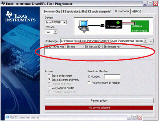
4. I tried Forced boot recovery mode (as suggested in SmartRF05 Evaluation Board User’s Guide Swru210a.pdf) however LED D6 never blinks.

Please help suggest how to recover this eval board?

THanks

Anubhav

  • Hi Anubhav,

    It is firmware (Z-stack I believe) on the CC2530EM that shows the CC2530's MAC address when you hold down the joystick during reset, not the SmartRF05EB firmware itself. The fact that you don't see it anymore might be because you've programmed the CC2530 with a different firmware. If you want this behavior back, you'll need to reprogram the CC2530 with the original firmware.

    The SmartRF05EB firmware displays the text you describe, "TexasInstruments SmartRF05EB CC2530" when it detects a mounted CC2530EM. 

    From what I understand, you have two SmartRF05EBs. Then you can reprogram the malfunctioning [EB1] one using the second SmartRF05EB [EB2] as follows. It's a two step procedure, one for the SmartRF05EB bootloader (which seems to be malfunctioning), and one for the SmartRF05EB application.

    Bootloader:

    1. Download the latest version of SmartRF Flash Programmer and install it
    2. Connect a flat cable from P3 on [EB2] to P2 on [EB1]. Make sure both EBs are powered up (and connected via USB)
    3. In SmartRF Flash Programmer, select Evaluation Board in the "What do you want to program?" drop-down.
    4. Click the "EB Bootloader" tab.
      Select [EB2] with a CC2511 connected ([EB1]). Select a four digit Board ID that is not used by any other of your devices.
    5. Select what flash image to program.
      Here you select "usb_bootloader_srf05eb.hex" located in the Firmware folder of the SmartRF Flash Programmer installation directory (e.g. C:\Program Files\Texas Instruments\SmartRF Tools\Firmware\usb_bootloader_srf05eb.hex )
    6. Select "Erase, program and verify" before clicking "Perform actions"
    7. If programming was successful, the board should appear under the "EB Application (USB)" tab with the Board ID you selected.

    Application:

    1. Under the "EB application (USB)" tab, select [EB1] as the device to program in the device list.
    2. Select what flash image to program, you'll find "cebal_fw_srf05eb.hex" in the same folder as the bootloader hex file
    3. Select "Erase, program and verify" before clicking "Perform actions"
    4. If programming was successful, the board should appear in the device list  with firmware revision of 0013 or higher.


    Hope this helps!

    Cheers,
    ABO

  • Hi ABO,

    The issue is that my device (SmartRF05 EB) is not getting detected by Windows rather it's getting detected as an Unknown device. When I try the programing steps suggested by your or by Evaluation Board User Guide if gives me following error (No device Selected): Please suggest appropriately.


    Thanks

    Anubhav

  • Hi again,

    You should make sure you have the latest version of SmartRF Flash Programmer (currently v1.10.2).

    In your first post, I understood that you have two SmartRF05EBs, is that correct? Further, I understood that one of them is recognized correctly by your computer software, while the other does not. If that is correct, one EB should show up under the "EB application (USB)" tab.

    If you connect a flat cable from the working EB (connector P3) to the non-working EB (connector P2) and power them up, you should see the working EB in the SmartRF Flash Programmer device list with "Chip type" stating CC2511. If that is the case, let me know.

    Kind regards,
    ABO 

  • Hi ABO,


    Thanks for your help. I am now able to program my second board properly and it working now.


    Thanks

    Anubhav

  • Hi,

    I have a similar problem, however the SmartRF05EB doesn't seem to be recognized afterwards either. I followed the steps provided here but with no success. 

    The D6 led is now blinking at a fast rate (6-8 times per second) and the LED3 remains on, the LCD after following the steps provided doesn't show anything.


    Thanks,

    P. Ferreira

  • Does the SmartRF05EB with fast blinking show up in the Device manager? The fast blinking suggests that the bootloader does not find a valid application image.

    If the SmartRF05EB appears in the Device manager, you can try these steps to program the application (also described above)

    1. Under the "EB application (USB)" tab, select the fast blinking EB as the device to program in the device list.
    2. Select what flash image to program, you'll find "cebal_fw_srf05eb.hex" from <SmartRF Tools>\Firmware... folder
    3. Select "Erase, program and verify" before clicking "Perform actions"
    4. If programming was successful, the board should appear in the device list  with firmware revision not saying N/A


    Br,
    ABO 

  • No it doesn't show up...

    I get this error:


    Thanks,

    P.F

  • Hi P,


    I'm quoting ABO here (from one of his previous posts inthis thread):

    "If you connect a flat cable from the working EB (connector P3) to the non-working EB (connector P2)

    and power them up, you should see the working EB in the SmartRF Flash Programmer device list with

    "Chip type" stating CC2511. If that is the case, let me know."


    Br,

    Igor

  • Correct.


    Here is the image:


  • Great.

    Now, click on "..." button to select an image, then browse for this file:

    C:\Program Files (x86)\Texas Instruments\SmartRF Tools\Firmware\SmartRF05EB\usb_bootloader_srf05eb.hex

    Select it, then click on Erase and program.

    Afterwards, disconnect the "problematic" EB and connect it directly to your PC with USB cable.

    Then run flash programmer and program EB  with:

    C:\Program Files (x86)\Texas Instruments\SmartRF Tools\Firmware\SmartRF05EB\cebal_fw_srf05eb.hex

    Tel me if it works.


    Br,

    Igor

  • It flashes correctly, however when I connect to pc via USB it stil isn't recognized.

  • BTW, have you tried to flush

    C:\Program Files (x86)\Texas Instruments\SmartRF Tools\Firmware\SmartRF05EB\cebal_fw_srf05eb.hex

    instead of

    C:\Program Files (x86)\Texas Instruments\SmartRF Tools\Firmware\SmartRF05EB\usb_bootloader_srf05eb.hex

    I know, it makes no sense, but can you try this as an experiment?


    Br,

    Igor

  • I will try this on Monday, since I don't have the equipment with me at the moment. What is suppose to be the outcome?

    Thanks,

    P. Ferreira

  • Hopefully it'll get your EB into a working state :)


    Br,

    Igor

  • Hi, I get the following message "Bootloader image too big. Max 6 kB.". Is there anything I can try next?

    Thanks,

    P. Ferreira

  • Hi,


    It was a stupid of me suggesting you to do such a thing, excuse me for that one.

    I did a little of research, please try to perform the steps described in

    SmartRF05 Evaluation Board User’s Guide, section 10 - Updating the firmware

    (particular the 10.1 part)

    Tell me if it works for you.


    Br,

    Igor


  • Yes, that works. USB (D6) Led is blinking at 1 second interval. Do I keep the jumper for next step (10.2)?

  • I'm assuming that you have powered EB with an USB cable (no other devices connected to EB)?

    While D6 is blinking, open the flash programmer, select "Program evaluation board" and then

    click on "update EB firmware", or instead the "update EB firmware" click on "EB Application (USB)"

    tab and program EB with valid firmware.

    Afterwards, turn EB off, set the jumper to its previous state, and power EB on.


    Br,

    Igor

  • Yes it's USB powered, however, I get "Device Unknown" from windows and it's not recognized in the Flash Programmer. The update firmware button isn't active since the device isn't detected.

    I must flash the problematic EB while connected to the non-problematic EB (10.2)? I have followed these steps before and have had no success.

    Can I try anything else?

    Thanks,

    P. Ferreira

  • So basically, once you connected the problematic EB to a normal working EB (as described in section 10.2)

    and you flushed the problematic EB with smartRFEB05 firmware, it still isn't recognized when you plug it

    into a PC with USB cable?

  • Yes, it still isn't recognized. The other user had the exact same problem, however this one won't get detected after the flash.

  • Is it came that way (with not working USB), or you tried to update a firmware and at some point it went wrong?

  • I never tried to update anything, I have only been running the SampleApp and SerialApp applications for testing purposes. I have had the board for over 6 months and no problem whatsoever.

    Thanks,

    P. Ferreira

  • Hi,


    Here is what I did to program one of my EB with a valid firmware:

    1. Power source jumper is in the 2-3 mode (USB/DC) and the EB is in power off state (P8 - OFF)
    2. I've removed the 22530Evaluation Module
    3. I've connected and USB cable from my PC to the EB
    4. I've short circuited pins 17 and 19 on P18 header and then I turned the potentiometer clockwise until it stopped.
    5. I've turned on the EB (P8-ON). No LCD display, and D6 blinks once in a second.
    6. I've opened the flash programmer and selected "program evaluation board" option, then I clicked on
      "EB Application (USB)". See the picture below
    7. Then I selected an image in the following path:
      C:\Program Files (x86)\Texas Instruments\SmartRF Tools\Flash programmer\Firmware\SmartRF05EB\cebal_fw_srf05eb.hex
      and clicked on "perform action button" and I waited until "SmartRF05EB firmware update OK" appeared in the status window.i
    8. I turned the EB of (P8-OFF)
    9. Unplugged the USB cable, removed the jumper from pin17 and 19, and moved the potentiometer to other position.
    10. I've turned on the EB, and that is the pictur I see in the flash programmer (where "EB firmware rev = 0013 indicates workin EB)
      :

    If it doesn't work for, I'm afraid that I won't be able to help you any more, as I ran out all the ideas.


    Br,

    Igor


  • Thanks for your effort, but that didn't work for me. I followed the steps precisely but to no avail.

    Do you know who I may contact to get further support?


    Thankyou,

    P. Ferreira

  • Not particulary, but I can suggest you two things:

    1. You can contact with whoever you purchased this Kit from (distributors?).
    2. Start a new thread, with a link to this thread, may be TI guys know additional
      magic tricks (like shorting two pins and turning the potentiometer clockwise...)

    Br,

    Igor 

  • You say the device appears as unknown, in the Device Manager, what PID and VID appears in the details of the device?

    Have you tried manually to install a driver for the device? You should choose driver from <SmartRF Tools install dir>\Drivers\cebal\win_xxx_ where xxx depends on your OS.


    Br,
    ABO 

  • I have the following value:

    Yes, I have tried to install the driver manually. First I removed the existing one, then chose manual install. Still not recognized, the one is detected an has the following value:


  • So, you've tried to do the following: Erase the 05EB and programmed it with a bootloader (using another 05EB).  When programmed with the bootloader, the USB LED rapidly blinks, but the device shows up as Unknown in Windows.

    What voltage levels do you have on the board (V_io, V_em, ...) with USB and batteries as source? If the levels are ~3.3 V, that is as expected. If not, then one of the voltage regulators may be broken.

    You can try to program the application onto the 05EB via another 05EB as follows: Go to "Program CCxxxx SoC ..." and select the System-On-Chip tab. Here you select cebal_fw_srf05eb.hex and the Append option. Does the board detect any of your EMs?


  • TIABO said:
    So, you've tried to do the following: Erase the 05EB and programmed it with a bootloader (using another 05EB).  When programmed with the bootloader, the USB LED rapidly blinks, but the device shows up as Unknown in Windows.

    Yes, I have tried to erase and program the bootloader using another 05EB (usb_bootloader_srf05eb.hex). The USB Led (D6) flashes rapidly, but the device still shows up as Unknown.

    TIABO said:
    What voltage levels do you have on the board (V_io, V_em, ...) with USB and batteries as source? If the levels are ~3.3 V, that is as expected. If not, then one of the voltage regulators may be broken.

    Where do I measure this (P3?) and with or without EM inserted?

    TIABO said:
    You can try to program the application onto the 05EB via another 05EB as follows: Go to "Program CCxxxx SoC ..." and select the System-On-Chip tab. Here you select cebal_fw_srf05eb.hex and the Append option. Does the board detect any of your EMs?

    This worked. I am able to program the application onto the problematic 05EB.

    However, the device is still "Unknown". 

  • P. Ferreira said:
    What voltage levels do you have on the board (V_io, V_em, ...) with USB and batteries as source? If the levels are ~3.3 V, that is as expected. If not, then one of the voltage regulators may be broken.

    Where do I measure this (P3?) and with or without EM inserted?[/quote]

    In both cases. It's just to verify that the board's voltage is correct. You can measure this on jumpers P11, P13 and P15.

    P. Ferreira said:
    You can try to program the application onto the 05EB via another 05EB as follows: Go to "Program CCxxxx SoC ..." and select the System-On-Chip tab. Here you select cebal_fw_srf05eb.hex and the Append option. Does the board detect any of your EMs?

    This worked. I am able to program the application onto the problematic 05EB.

    However, the device is still "Unknown". [/quote]

    It is expected that the device is still unknown, the USB library is located in the bootlaoder. Does the 05EB detect EMs you mount on it?

    Do you observe the same behavior on all computers you connect the 05EB to? Have you tried different USB cables (just to rule out the unlikely possibility that your USB cable is the cause)?

    It sounds like it's a hardware issue, the USB MCU's USB controller may be broken due to ESD (any bad storms lately? :) ). You should however verify that the all the components related to USB are properly mounted? (R9, R10, R11, R12, C2 and C3). (For SmartRF05EB schematics, see appendices in SmartRF05EB User's Guide).

  • Checked the voltages, they are 3.3 V with USB and 3.26 V with battery. Yes the 05EB board detects EM device, and works. Checked some other computers and changed cable, the problem still is present. No storms...however I was using a hub, maybe too many devices attached at the time it failed?

    The resistors are ok, haven't checked the capacitors don't have a multimeter capable of doing this yet.


    Anything else I can try? thanks

  • Hi,

    i have the similar problem.

    i tried all step previous posts . my PC know my Smart RF05EB 1.8.1. my problem is that any of EM board doesn't detect. also  i connect EB2(not work)  P3 to EB1 (P2) and it is detect cc2511.  i tried bootlood from EB1 and firmware update but it is still the same.  but there is a difference when i mount an cc2530 to P5-P6, LCD turn off and flash programmer not detect cc2530. but i connect EB1(P2)   from P3. The LCD is working but NO EM detected. May be this difference help us :(   

  • ismail HANCI; said:

    Hi,

    i have the similar problem.

    i tried all step previous posts . my PC know my Smart RF05EB 1.8.1. my problem is that any of EM board doesn't detect. also  i connect EB2(not work)  P3 to EB1 (P2) and it is detect cc2511.  i tried bootlood from EB1 and firmware update but it is still the same.  but there is a difference when i mount an cc2530 to P5-P6, LCD turn off and flash programmer not detect cc2530. but i connect EB1(P2)   from P3. The LCD is working but NO EM detected. May be this difference help us :(   


    i solved my problem. i tried all steps in user guide and this post about bootloader and firmware. But there is no success. Because My jumper settings are wrong.

    user guide includes the correct jumper settings.

    For SmartRF05EB 1.8.1.1  =>P10  all jumper mount and  

       P1 => 5-7 -17-18-19...35.

    Now it is working.

  • Great post , very helpful ... successfully solved our problems .

    Respect .

    TEAM JKNV