This thread has been locked.

If you have a related question, please click the "Ask a related question" button in the top right corner. The newly created question will be automatically linked to this question.

Enabling POWER_SAVING causes intermittent BT connection fail.

Other Parts Discussed in Thread: CC2541, CC2541DK-MINI, CC2540, CC2541S

Hey guys,

We're seeing a dropped BT connection anywhere from ~10sec to several minutes, related to POWER_SAVING.  We believe we have a HW issue related to the internal voltage regulators.

We have designed a circuit exactly the same as the CC2541 KeyFob reference design.  The only differences are the board layout, the 32.768KHz crystal, and slight differences in the balun component values. 

The SW is the default BLE stack v.1.3 KeyFob app, with very minor changes like turning on initial advertising and commenting out the accelerometer init code (no accel. in our design), and just replacing the accel read function with hardcoded, static incrementing x,y,z values.  We have it communicating with the default TI iPhone app showing these values.

It runs great on the CC2541DK-MINI KeyFob eval board, BUT running the exact same code (which just pumps out X,Y,Z) on our board fails after a random period of time only when POWER_SAVING is enabled.  

See our previous thread: http://e2e.ti.com/support/low_power_rf/f/538/p/256304/902292.aspx#902292

Now, if I change the code in hal_sleep.c to #define HAL_SLEEP_TIMER  PM1  (instead of PM2), the code runs OK on our board for much much longer.   My understanding is that we're now ensuring that the internal voltage regulators remain ON (PM1) during sleep.

What could be causing troubles with the internal voltage regulators?  Any thoughts out there?

NOTE:  We believe we've eliminated the 32.768KHz crystal as the problem since we injected a perfect 32.768001KHz (50% duty cycle) signal from a signal generator per app note AN#119.   We've also output it on P0.0 via CKOEN.  We also previously swapped the crystal for the exact one used on the CC2541DK EB… and tried different loading caps between 15pF and 18pF.   All is good… seeing a really nice 32.768KHz clock.

ALSO NOTE: Note we are able to replicate this problem on all our boards (about 10).

Any thoughts out there?

Many Thanks!
Brian

  • Hello Brian,

    Still no luck?  You have outlined the problem quite clearly now.

    The one thing I'm not clear on with your running the same code on the Keyfob.  Are you running the exact same code that only pumps out X, Y, Z on the Keyfob?

    Also, in relation to the battery, are you using the same AA batteries on the KeyFob when you do your test?

    That would completely eliminate the code and the hardware.  The problem would be with your board layout and design unless all the CC2541 where somehow damaged when they were placed on the board.

    Thanks,

  • Hello back,

    Yeah, this one is tough.  Really struggling on it.  Thanks for your help!

    Yes, we are running the exact same code on both the CC2541DK-MINI KeyFob eval board and our board.  I've also stripped down the eval board to match ours, i.e. removed accel., voltage regulator; that's pretty much it.

    Yes, we are using the same AA batteries on the KeyFob eval board and ours.  I connect the positive side of the battery pack to VCC, pin2 of the test header.

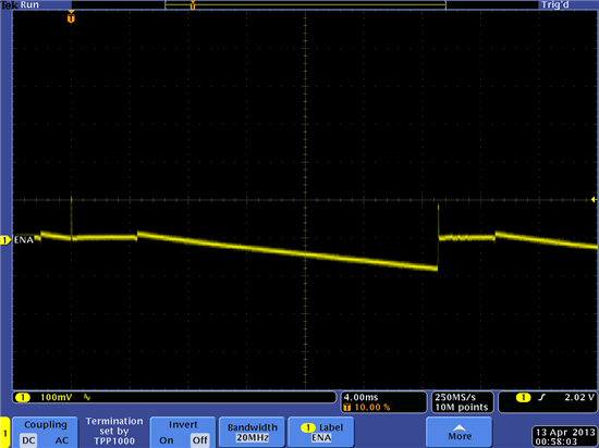
    Also, some more investigation today.  We scoped-out the DCOUPL pin.  We're measuring 1.917V.   Not seeing any significant noise or any differences compared to the KeyFob reference eval board.   See attached screen capture.

    Note, we're seeing the fail on all of our boards.  We also lifted one of the CC2541 chips and verified we had a good solder on the ground pad.

    Another note.  We verified the RBIAS resister was within 1% spec of 56K.

    Anything else left to try?  Is there anyone there at TI that could perhaps take a look at our board layout/gerber files?

    Cheers,
    Brian

  • Oops... attaching scope screenshot.  This is DCOUPL pin during advertising mode.

     Thanks,

    Brian

  • Hey Guys,

    We're really stuck on this one.   TI Folks!  Is it possible to send some PDF of our gerbers for a quick review?

    Does anyone really know why this gets called?  LL_STATUS_ERROR_CONN_TIMING_FAILURE

    With the packet sniffer, we're not seeing any messages from the master (iPhone) that could close the link.  It seems to be on our side, from the peripheral.   In fact, we keep seeing connection packets from the iPhone for a number of seconds after we get this error and the link closes.

    Some other things we tried...

    ** I completely removed the 1uF DCOUPL caps (by accident) and ran it without it.  It made no difference.  It actually ran for about five minutes... pretty long time WITHOUT any decouple cap on that DCOUPL pin.

    ** I measured the voltage at the RBIAS pin and our board is about 0.93V.  The eval board is about 1.04V.   And supposedly it should be 1.15V according to this post:
    http://e2e.ti.com/support/low_power_rf/f/538/t/198721.aspx

    ** I can't get it to fail with the debugger connected (except once or twice after hours) a while back.

    Again, the exact same code runs great on the evaluation board.   And it also runs great if we turn off POWER_SAVING.

    Any other low-level things we could try? 

    Thanks,
    Brian

  • Hi Brian,

    I think I have seen the error

    #define LL_STATUS_ERROR_CONN_TIMING_FAILURE            0x3F // MAC Connection Failed

    when I disrupt the RF Core ISR by blocking in a higher priority ISR for too long.

    This leads me to lean toward a timing/clock related issue in your case.

    -Tyler

  • Thanks for the message Tyler!  Really appreciated.

    Interesting.  Hm.  We are using just the KeyFob code.  Runs great on the evaluation board, but not ours.

    I wonder... can you think of a way to disable all other possible ISRs except the RF Core ISR?  Or some way to just rule out the possibility of that happening?

    Is there anything about going in and out of sleep that could delay the RF Core ISR?  Because, when we disable POWER_SAVINGS (don't include that flag in the preprocessor settings), it runs great on our board.

    Thanks,

    Brian

  • Hi Brian,

    I'm not too familiar with the keyfob app, but if you execute the following at the end of your initialization routine, that should rule out the blocking ISR issue.  This snippet will make the interrupt priority group 0 (RF Error, RF, DMA) highest priority and all other interrupts the same, lowest, priority.

    IP0 = 1;

    IP1 = 1;

    You said you're 32 KHz xosc seems fine, have you checked the 32 MHz?  Problems when you turn on sleep point toward the 32KHz, but if you feel confident you ruled that out, you might want to check out the 32 MHz including load capacitance,etc.

    When going to sleep (hal_sleep.c->halSleep()), the driver will attempt to figure out whether or not it needs to wake up for an RF event and will set the 32KHz-based sleep timer to fire before the event if necessary.  One thing might block here is extended time for the 32MHz clock to stabilize after coming out of sleep.

    Another thing to try which might give some hints about a clock/timing problem is to make your connection interval very short so that any clock inaccuracy is de-emphasized.  Also ensure that slave latency is set to 0.

    -Tyler

  • Hi Tyler,

    This is super helpful.   Looks like we might have gotten to the bottom of this.  

    We changed the loading caps for the 32MHz crystal from 18pF caps to 13pF caps and I now have our board running overnight. Does this seem to make sense that this might have fixed the problem?  Could it be that the 32MHz crystal took too long to stabilize with 18pF caps?  

    Note that we're using a similar crystal (both are 10pF parts).

    The reference design uses an Epson part:
    http://www.eea.epson.com/portal/pls/portal/docs/1/1529449.PDF
    while our design uses an Abracon part:
    http://www.abracon.com/Resonators/ABM11.pdf

    We had selected 18pF loading caps for our 32MHz crystal because we thought we had a lot less parasitic loading capacitance on our board compared to the reference design since our traces are a lot shorter.  Maybe this is not the case.

    Many thanks Tyler and everyone who has helped here.

    Brian

  • Finally!  I think we got it here guys.  We replaced the crystal with the exact one used in the reference design (and moved to 13pF caps) and we now have it running our tests overnight and things are working great.  But we're not completely sure why.

    We were using this Abracon crystal:
    http://www.abracon.com/Resonators/ABM11.pdf

    We switched to this Epson part in the reference design:
    http://www.eea.epson.com/portal/pls/portal/docs/1/1529449.PDF

    The only real difference we see between that the Abrocon part that we were using has slightly higher equivalent series resistance (spec is 80ohm), whereas the Epson part is around 60ohm. 

    We think the issue is around the start-up time of the crystal with Power Savings enabled.  Any thoughts out there?  Note, we have measured both crystal accuracies and they are around 15-20ppm -- well within the 40ppm spec, so I think we're OK there.

    IS the ESR of the crystal significant here for this design?

    Thanks!
    Brian


  • Brian,

    I'm glad you found the problem!  I don't know enough to comment on whether ESR matters, but you should be able to gather some empirical data by observing the actual time-to-stabilization for both crystals during wake up.

    You can toggle a GPIO around the call LL_PowerOnReq( wakeForRF ) in hal_sleep.c  and observe it with a scope or LA.  I believe in that function is where the sleep driver spins waiting for the clock to stabilize in the 1.3 blestack.

    -Tyler

  • FWIW, I have been involved on a project which had a similar occasional dropped connection using the CC2541. After much debugging, we found that the macro which defines how much to adjust the sleep time within halSleep() (see hal_sleep.c) was not quite adequate in all situations.  For the CC2541, the code subtracts 25 32 kHz ticks from the requested value which purportedly accounts for the time lost in the beginning of halSleep() prior to actually putting the processor to sleep.  We measured times as high as 28 ticks and found that bumping the value up to around 35 ticks (the value used for the CC2540) made our dropped connections disappear.

    From what we could see on the scope, when we dropped a connection, we were waking up just a tad too late for the next radio event and the 32 MHz XTAL oscillator was not up and stabilized quite soon enough for the radio communication to work reliably.

    Have no idea if this might be a contributing factor, but something that is easy to measure and or adjust.

    #if defined( CC2541) || defined( CC2541S )
    #define HAL_SLEEP_ADJ_TICKS                 25                    // default sleep adjustment, in 32kHz ticks

                                                                                   ^^ The above value was too low in our case.
    #else // CC2540
    #define HAL_SLEEP_ADJ_TICKS                 35                    // default sleep adjustment, in 32kHz ticks
    #endif // CC2541 || CC2541S