This thread has been locked.

If you have a related question, please click the "Ask a related question" button in the top right corner. The newly created question will be automatically linked to this question.

increasing range of 13.56 Mhz anytenna

Other Parts Discussed in Thread: TRF7960

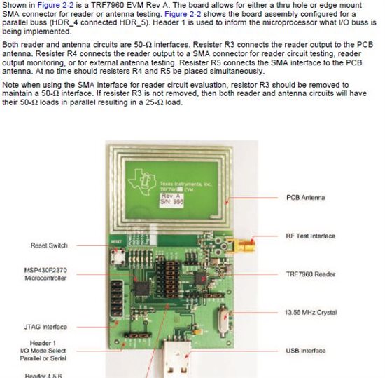
I am working with TRF7960Evm and want to increase range of evm by connecting an external antenna so my range increases to near about 15 cm for tag detection , now while going through this Pdf:

http://www.ti.com/lit/an/sloa135/sloa135.pdf

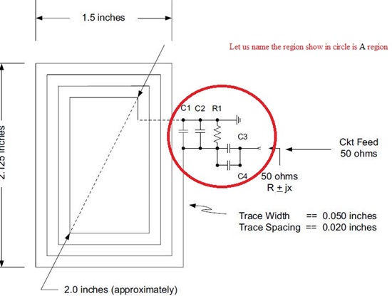
i found that antenna trace is directy proportional to its range , i have following doubts here:

1.) If  connect a large antenna externally to it will it work on power output given by board or we need to increase power also externally,

2.) from where i can get readymade external antenna which i can connect directly with it and increasse the range..

thanks in advance.

  • Hello

    In my application based on  library automation using trf7960 , initally i am working trf7960 evm now i have following doubts:


    1) What is the maximum range of antenna connected with TRF7960 Evm , is it same as given in this post:

    http://e2e.ti.com/support/low_power_rf/f/667/t/88470.aspx

    i.e 300* 300 cm if i go according to this post and   6813.TI HF Reader and HF Tag Read_Ranges_01_31_2008.pdf  i get to know that by using diifernt tag i can increase range without changing antenna , i am using this tag now :

    RI-INL-R9QM,

    RI-TRP-RFOB,

    RI-TRP-W4FF 

    I am not able to detect beyond 3 cm with this tag, i want to know from where i can find tag given in pdf on ti website to purchase ,


    thanks in advance.


  • The range is proportional to the size of the antenna of both the reader and the tag.  It is important to consider the size of the tag antenna as well as this plays a part in sizing up your reader antenna.  Very small tags require a dense field to couple energy properly, so you must use a smaller antenna size.  To attain 15cm range with the TRF7960EVM and an external antenna, you will need to use a larger tag size (45mm x 45mm or larger). 

    1. If you are using a reasonable size tag, the 200mW output power from the TRF7960 is enough to drive antenna of about 300mm x 300mm max.  For smaller tag sizes, an antenna of this size will not provide a dense enough magnetic field which results in reads only occuring in the corners of the antenna. 

    2. Feig offers some great antennas.  They are not low cost though.  Jogtek has some antennas as well, but I don't see them listed on the website.

    http://www.feig.de/en/products/obid/product-areas/obid-i-scan-hf/mid-range-antennas.html

    http://www.jogtek.com/ 

  • Observed free space read range of the TRF7960EVM with the onboard antenna is attached.  You will also see read range with a smaller antenna(20mm x 20mm).  The read ranges in the post you mention uses a 300mm x 300mm antenna. 

    I think you are mistaken on the tag part numbers you provided.  RI-INL-R9QM, RI-TRP-RFOB, and RI-TRP-W4FF are all low frequency tags and will not be read by the TRF7960.   The HF tag that provides the greatest read range is our 76mm x 45mm inlay.  You can find the different varioations of this tag at the link below.  FYI, the "B" version of the tag is offset tuned for integration into a PVC card.   

    http://focus.ti.com/paramsearch/docs/parametricsearch.tsp?family=rfid&sectionId=475&tabId=2102&familyId=1352     

    TRF796x EVM Read Ranges.pdf
  • Thanks Eddie for such a prompt  and informative reply , it helps very much , now according to your reply i am able to get this thing :

    1) for reading range of 15 cm i need to use large tag with the external antenna( 300mm * 300mm) attached to trf796 evm , ( i dont need to use amplifer here)

    2.) According to the pdf , i can have 12 cm read range with the default antenna which is (20 mm * 20mm) ..

    Few doubts here :

    a) Do texas manufacture antenna also for rf ,as feig antenna are very much costly , there is any way i can make antenna myself or any other substitute for my requirement basically i need to detect stack of book with tag attached to them with one antenna, any help will be greatly appreciated.

    b.) according to post suggested by you i can use this tag with my antenna size 300mm* 300mm( external ) :

    http://www.ti.com/product/ri-trp-0106?

  • 1. Yes, this is correct.

    2. With the TRF7960EVM, the antenna is 55mm x 40mm.  The read range is 11cm with the 76mm x 45mm tag.  With a reader antenna of 20mm x 20mm, the read range is 8cm for the 76mm x 45mm tag. 

    a. No, we do not manufacture any HF antennas.  Yes, you could design your own antenna on a PCB or use copper magnet wire.  Take a look at the antenna tuning section of the TRF7960ATB users guide.  Reading a stack of tags brings in some new challenges as well.  You must provide enough field strength to power all the tags within the antenna field.  Depending on how many tags will be in the stack, you may require a power amplifier.  Again, larger tags are preffered since the larger the tag, the less field strength required to receive a response.  

    TRF7960ATB Users Guide: http://www.ti.com/litv/pdf/slou297 

    b. No, the RI-TRP-0106 is an LF(134.2kHz) tag.  TRF7960 is an HF(13.56MHz) reader.

    It sounds like you would be making a product similar to the 3M mini tracking pad.  You can find some details on this product below.  It also uses a 200mW output power RFID transceiver.  The antenna on this tracking pad is 150mm x 150mm and it is specified to read up to 15cm.  You could probably create a similar sized antenna for your application.

    http://www.digikey.com/us/en/ph/3M/tracking_pad.html

  • Hello Eddie 

     first of all , sorry for my delay response basically i was struck somewhere else and also i was going through various pdf that i can find about TRF7960 and was analyzing the evm in lab through spectrum analyzer , now i am able to Conclude many things and looks like i have found a way of doing my job which is like this:

    1.) I will use extrernal antenna with evm , now for that as shown in image (from user manual ) For this i am able to conclude i need to remove Resistance R3 and and also R5 Resistor.( see if i am correct here regarding R5 resistor ?)

                                                            i 


    2) I also need to design my antenna , the things that i am able to conclude form antenna matching tutorial is i need my antenna input impedence +( the ckt as show in figure A Region which i will connect should connect or design ) should add up to 50 ohms.( basically I need to confirm here  that i will  connect external ckt with my antenna to make its input impedence +.should adds up to 50 ohms.) and the whole external antenna + ckt will be connected to evm through sma connector )


    3.) How i can calculate input impedence of my antenna , if i don't have VIM with me , as i will be designing Loop antenna  myself( 300 mm * 3mm) of FR4 material, Er = 4.5, with a material thickness of 0.62 inches. The board design is 2 layer design (layer 1 top, & layer 2 bottom), with 2 oz copper. ( these are the specification as given in pdf of antenna matching)


    bye and my question is big and bit silly, but i am definately sure it will help more novice visiting here for Rf.

  • I am working on TRF7960 evm  , i need to increase the range of antenna by connecting the external antenna to it , As I am a novice so i was going through various pdf that i can find about TRF7960 and was analyzing the evm in lab through spectrum analyzer , now i am able to Conclude many things and looks like i have found a way of doing my job which is like this:


    1.) I will use extrernal antenna with evm , now for that as shown in image (from user manual ) For this i am able to conclude i need to remove Resistance R3 and and also R5 Resistor.( see if i am correct here regarding R5 resistor ?)


                                                            i 


    2) I also need to design my antenna , the things that i am able to conclude form antenna matching tutorial is i need my antenna input impedence +( the ckt as show in figure A Region which i will connect should connect or design ) should add up to 50 ohms.( basically I need to confirm here  that i will  connect external ckt with my antenna to make its input impedence +.should adds up to 50 ohms.) and the whole external antenna + ckt will be connected to evm through sma connector )


    3.) How i can calculate input impedence of my antenna , if i don't have VIM with me , as i will be designing Loop antenna  myself( 300 mm * 3mm) of FR4 material, Er = 4.5, with a material thickness of 0.62 inches. The board design is 2 layer design (layer 1 top, & layer 2 bottom), with 2 oz copper. ( these are the specification as given in pdf of antenna matching)


    bye and my question is big and bit silly, but i am definately sure it will help more novice visiting here for Rf.


  • 1. Yes, you should remove R3 and R5.  R5 should not be populated by default. 

    2.  Correct, your matching circuit should match the antenna to 50 ohm impedance.  You can use a smith chart simulator program to get rough values.  You can find a useful smitch chart from the link below.

    http://fritz.dellsperger.net/

    3.  It is generally best to aim for about 1uH inductance of the coil and then adjust your tuning components.  For 300mm x 3mm antenna, I suggest 2 turns with  0.4mm trace width.  According to the calculator tool below, this should result in about 969nH.  You can convert this to the approximate complex impedance by using the formula 2*pi*fL.  This equates to ~ 1 + j82.51.  I have plotted this with the smith chart software and came up with tuning values.  This plot and tuning values are attached.  Please note that this is all based on calculations and will likely not be a perfect match.  It is best to measure the complex impedance of the antenna coil @ 13.56MHz using a network analyzer. 

    http://e2e.ti.com/members/693639/files/Calculate_5F00_L.zip.aspx 

  • Not sure if 300mm x 3mm is a typo or not.  An antenna this skinny will not acheive very great range! 

  • Thanks eddy for such a detailed and nice reply , Basically i mistyped antenna size it will be (300 mm* 300mm) according to the Ti Hf Reader and RF read ranges pdf , so i am extremely sorry for it , and u did the whole tunning for  (300 * 3 mm ) .

    Kindly give your design suggestion for 300mm*300mm the way you have given for 300mm * 3 mm , what is the preferable material i should use for fabrication of antenna :copper or Alluminium ?

    Your line on previous post i.e:"It is generally best to aim for about 1uH inductance of the coil "Does it mean I should adjust my trace width and turns in such a way so to achieve this 1uH, do the material used in fabrication of antenna other then pcb will not effect anything of antenna impedence , what basically antenna trace size stand s for is it  trace width or trace spacing?


    hoping for a positive reply

    bye 

  • For 300x300, I suggest 1 turn with 2mm trace width.  This should get you close to 1uH.  I have attached one suggested tuning plotted on the smith chart. 

    I suggest using copper.  The calculations are based on an copper PCB.  You could also build this antenna with copper tape and be pretty close to the calculation.

    Yes, you can adjust the trace width to increase/decrease inductance.  I would not worry as much about the trace spacing.  It is generally acceptable to use the same trace spacing as your trace width, but in the case of an antenna with such large dimensions, it will only be 1 turn anyway.   


  • Thanks eddy antenna work fine for me , I use copper pcb . there are slight problem with gui shipped with trf7960 evm i am working on it to make a nice gui will be completed in 25 days and then will upload it . can u tell me is there any way i can replicate evm at my end as i need two evm for my resarch purposes or should i simply  replicate it as pcb design is given or it has more technicalities attached to it.

  • Yes, you could just copy our EVM exactly if you would like.  I have attached the gerbers.  7801.TRF796x_EVM_Rev_A1_Gerbers.zip