Hi all,
I'm doing a project that use FFT and IFFT.
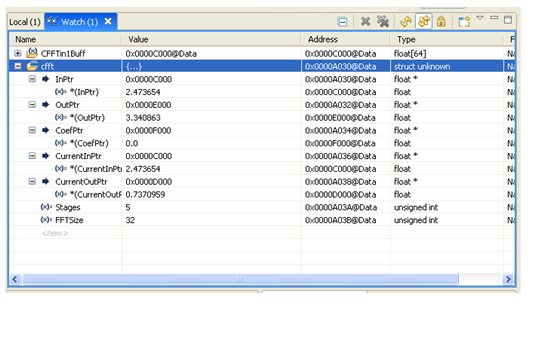
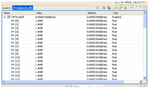
First I try with the example from FPU library ("2833x_RFFT_ADC_RT") and the result is very good. But after that I tranfer the Rfft_f32u function to Cfft_f32u,the FFT can't work properly.
Please help me solve this problem!
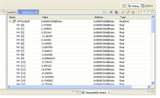
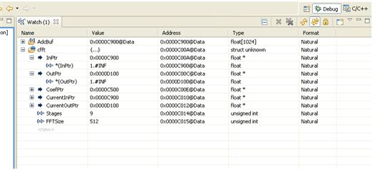
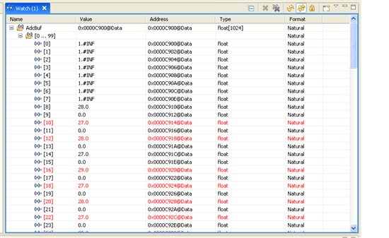
I attached the result from Watch wimdow:
This is the code of my program:
#include "Lab.h" // Main include file
#define F_PER_SAMPLE 48000.0L/(float)FFT_REAL_SIZE //Internal sampling rate is 48kHz
//RFFT_ADC_F32_STRUCT rfft_adc;
CFFT_F32_STRUCT cfft;
float32 FFTReal_out[2*FFT_REAL_SIZE]; //Calculated FFT result
float32 FFTReal_CosSinTable[FFT_REAL_SIZE]; //Coefficient table buffer
float32 FFTReal_Magnitude[FFT_REAL_SIZE/2+1]; //Magnitude of frequency spectrum
float32 FFTReal_Mag_Monitor[FFT_REAL_SIZE/2+1];
float32 THD[30];
//--- Global Variables
float32 AdcBuf[2*ADC_BUF_LEN]; // ADC buffer allocation
volatile Uint16 FFTStartFlag = 0; // One frame data ready flag
Uint16 DEBUG_TOGGLE = 1; // Used in realtime mode investigation
Uint16 k=0;
Uint32 PwmDuty; // measured PWM duty cycle
Uint32 PwmPeriod; // measured PWM period
// Prototype statements for functions found within this file.
interrupt void adc_isr(void);
/**********************************************************************
* Function: main()
*
* Description: Main function for C2833x Real-time RFFT
**********************************************************************/
void main(void)
{
Uint16 i;
float32 freq; // Frequency of single-frequency-component signal
//--- CPU Initialization
InitSysCtrl(); // Initialize the CPU (FILE: SysCtrl.c)
InitGpio(); // Initialize the shared GPIO pins (FILE: Gpio.c)
InitPieCtrl(); // Initialize and enable the PIE (FILE: PieCtrl.c)
InitWatchdog(); // Initialize the Watchdog Timer (FILE: WatchDog.c)
//--- Peripheral Initialization
InitAdc(); // Initialize the ADC (FILE: Adc.c)
InitEPwm(); // Initialize the EPwm (FILE: EPwm.c)
// Interrupts that are used in this example are re-mapped to
// ISR functions found within this file.
EALLOW; // This is needed to write to EALLOW protected register
PieVectTable.ADCINT = &adc_isr;
EDIS; // This is needed to disable write to EALLOW protected registers
cfft.InPtr = &AdcBuf[0]; //Input buffer
cfft.OutPtr = &FFTReal_out[0]; //Output buffer
cfft.CoefPtr = &FFTReal_CosSinTable[0]; //Twiddle factor
cfft.FFTSize = FFT_REAL_SIZE;
cfft.Stages = FFT_REAL_STAGES; //Real FFT stages
//Magnitude output buffer
CFFT_f32_sincostable(&cfft); //Calculate twiddle factor
//Clean up output buffer
for (i=0; i < FFT_REAL_SIZE; i++)
{
FFTReal_out[i] = 0;
}
//Clean up magnitude buffer
for (i=0; i < FFT_REAL_SIZE/2; i++)
{
FFTReal_Magnitude[i] = 0;
}
//--- Enable global interrupts
asm(" CLRC INTM, DBGM"); // Enable global interrupts and realtime debug
//--- Main Loop
while(1) // endless loop - wait for an interrupt
{
if(FFTStartFlag) // If one frame data ready, then do FFT
{
CFFT_f32u(&cfft); // This version of FFT doesn't need buffer alignment
cfft.CurrentOutPtr = &FFTReal_Magnitude[0];
CFFT_f32_mag(&cfft); // Calculate spectrum amplitude
freq = FFTReal_Magnitude[1];
FFTReal_Mag_Monitor[0]=FFTReal_Magnitude[0]*24.0/4095.0;
for(i=1;i<FFT_REAL_SIZE/2+1;i++)
{ FFTReal_Mag_Monitor[i]=FFTReal_Magnitude[i]*48.0/4095.0;
if (i<31)
{
THD[i]=FFTReal_Mag_Monitor[i]/FFTReal_Mag_Monitor[1]*100.0;
}
//Looking for the maximum valude of spectrum magnitude
if(FFTReal_Magnitude[i] > freq)
{
freq = FFTReal_Magnitude[i];
}
}
THD[0]=FFTReal_Mag_Monitor[0]/FFTReal_Mag_Monitor[1]*100.0;
FFTStartFlag = 0; //Start collecting the next frame of data
}
asm(" NOP");
}
} //end of main()
interrupt void adc_isr(void)
{
static float32 *AdcBufPtr = AdcBuf; // Pointer to ADC data buffer
static volatile Uint16 GPIO34_count = 0; // Counter for pin toggle
PieCtrlRegs.PIEACK.all = PIEACK_GROUP1; // Must acknowledge the PIE group
//--- Manage the ADC registers
AdcRegs.ADCTRL2.bit.RST_SEQ1 = 1; // Reset SEQ1 to CONV00 state
AdcRegs.ADCST.bit.INT_SEQ1_CLR = 1; // Clear ADC SEQ1 interrupt flag
//--- Read the ADC result
*AdcBufPtr++ = AdcMirror.ADCRESULT0; // Read the result
*AdcBufPtr++=0;
k++;
//--- Brute-force the circular buffer
if( k==512 )
{
AdcBufPtr = AdcBuf; // Rewind the pointer to the beginning
FFTStartFlag = 1;
k=0; // One frame data ready
}
//--- Example: Toggle GPIO18 so we can read it with the ADC
if(DEBUG_TOGGLE == 1)
{
GpioDataRegs.GPATOGGLE.bit.GPIO18 = 1; // Toggle the pin
}
//--- Example: Toggle GPIO34 at a 0.5 sec rate (connected to the LED on the ControlCARD).
// (1/48000 sec/sample)*(1 samples/int)*(x interrupts/toggle) = (0.5 sec/toggle)
// ==> x = 24000
if(GPIO34_count++ > 24000) // Toggle slowly to see the LED blink
{
GpioDataRegs.GPBTOGGLE.bit.GPIO34 = 1; // Toggle the pin
GPIO34_count = 0; // Reset the counter
}
return;
}
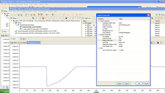
BTW, I have another question about "Graph" in CCS4.0. That is I can't make the data from ADC running online but just show the result at one time.
Regards,
Hoang Cuong.