This thread has been locked.

If you have a related question, please click the "Ask a related question" button in the top right corner. The newly created question will be automatically linked to this question.

I2C trouble on TMS320F28027 piccolo

Other Parts Discussed in Thread: TMS320F28027

Hi

When writing data on the I2c bus in what order should i setup the i2c module?

The way i have it right now is. 1. set slave address register and data counter. 2. set mode register 3. start writing data to data transmit register.

The other issue i am having is that once my data has been sent the bus is still being held busy (i can see from the status register), and I can't seem to free up the bus, even clearing the Bus Busy bit in the status register doesn't help.


Thanks


Jordan

  • Jordan, I usually follow this sequence

      I2caRegs.I2CSAR = I2C_SLAVE_ADDR;    //Set slave address
       I2caRegs.I2CCNT = DATA_BYTES;          //Set counter to the number of bytes to be transferred
       I2caRegs.I2CDXR = data[0];                     //Load first data byte into I2CDRR         
       I2caRegs.I2CMDR.bit.TRX = 1;                 //Set to Transmit mode
       I2caRegs.I2CMDR.bit.MST = 1;                //Set to Master mode
       I2caRegs.I2CMDR.bit.FREE = 1;              //Debugger will not halt the bus on a breakpoint
       I2caRegs.I2CMDR.bit.STP = 1;                //Master must release bus once Tx is complete , i.e. I2CCNT =0
       I2caRegs.I2CMDR.bit.STT = 1;                 //Send the start bit, transmission will follow

    You have to set the STP bit in the mode register so that the master will free the bus once transmission is complete, else it will continuously appear busy (BB = 1). Alternatively you can clear the BusBusy bit by writing a 1 to the STP bit of the I2CMDR in the debugger window

  • Thanks for the reply vishal.

    so you set the mode register after you have written data in the transmit register? That has been kind of confusing me since if I have more than 1 byte wouldn't it override the previously written data in the I2CDXR?


    Jordan

  • Hi Jordan, If you want to send multiple data you have to check the status of the Tx shift register before writing the next byte to I2CDRR. Same setup as before, then

    for(i=0; i<N ;i++){

    while(I2caRegs.I2CSTR.bit.XRDY == 0){}; //Do nothing till bus is free
    I2caRegs.I2CDXR = data[i]; //Next data byte

    }


    Alternatively, you can set it up in FIFO mode, where you can write 4 data points to the fifo and then transmit. Heres an example

    I2caRegs.I2CSAR = I2C_SLAVE_ADDR; //Set slave address
       I2caRegs.I2CCNT = I2C_NUMBYTES; //Numbe rof bytes to transfer
       I2caRegs.I2CFFTX.all = 0x6000; //enable FIFO mode and reset TX FIFO
       I2caRegs.I2CDXR = data[0] //Send data[0-3]
       I2caRegs.I2CDXR = data[1] //Store in next FIFO level
       I2caRegs.I2CDXR = data[2] //Store in next FIFO level
       I2caRegs.I2CDXR = data[3] //Store in next FIFO level
       I2caRegs.I2CMDR.bit.TRX = 1; //Set to Transmit mode
       I2caRegs.I2CMDR.bit.MST = 1; //Set to Master mode
       I2caRegs.I2CMDR.bit.FREE = 1;//Run in FREE mode
       I2caRegs.I2CMDR.bit.STP = 1; // release the bus after Tx
       I2caRegs.I2CMDR.bit.STT = 1; //Send the start bit, transmission will follow

    You can reload the FIFO after this for the next 4 bytes and so on


    Hope this helps!

  • Thanks for the reply Vishal

  • ok that worked.... now im having trouble reading data from eeprom. I am not using a state machine since I am going for something time critical.

    Here is my read function.... 


    I2caRegs.I2CCNT = 3;

    I2caRegs.I2CMDR.bit.STT = 1; //Send the start bit, transmission will follow

    I2caRegs.I2CDXR = CtrlByte1; //Send control byte

    I2caRegs.I2CDXR = Addr + i; //Store in next FIFO level


    I2caRegs.I2CMDR.bit.TRX = 1; //Set to Transmit mode

    I2caRegs.I2CMDR.bit.MST = 1; //Set to Master mode

    I2caRegs.I2CMDR.bit.FREE = 1; //Run in FREE mode

    I2caRegs.I2CMDR.bit.STP = 0; // release the bus after Tx

    I2caRegs.I2CMDR.bit.STT = 1;


    I2caRegs.I2CDXR = CtrlByte2;

    I2caRegs.I2CMDR.bit.TRX = 0; //Set to Receive mode

    I2caRegs.I2CMDR.bit.MST = 1; //Set to Master mode

    I2caRegs.I2CMDR.bit.FREE = 1; //Run in FREE mode

    I2caRegs.I2CMDR.bit.STP = 1; // release the bus after Tx


       if(I2caRegs.I2CSTR.bit.RRDY == 1)

       {

       rxBuff[i] = I2caRegs.I2CDRR;

       }


  • See attached code snippet. You have to send the read address to the eeprom before you read from it

    //////////////////////////
    // Write data to EEPROM //
    //////////////////////////
    //I2C_SLAVE_ADDR = 0x50 address of the EEPROM
    //I am writing 'h','e','l','l','o' to the EEPROM and then read it back later
    //I2C_NUMBYTES = 5
    //[MemoryHighAddr:MemoryLowAddr] -Address within the eeprom where you want to read/write
    //Data[] has the word 'hello' and RxdData[] will store data read from the eeprom
       I2caRegs.I2CSAR = I2C_SLAVE_ADDR; 			//Set slave address
       I2caRegs.I2CCNT = I2C_NUMBYTES + 2; 			//Set count to 5 characters plus 2 address bytes
       I2caRegs.I2CDXR = MemoryHighAddr;			//Send eeprom high address            
       I2caRegs.I2CMDR.bit.TRX = 1; 				//Set to Transmit mode
       I2caRegs.I2CMDR.bit.MST = 1; 				//Set to Master mode
       I2caRegs.I2CMDR.bit.FREE = 1;				//Run in FREE mode
       I2caRegs.I2CMDR.bit.STP = 1; 				//Stop when internal counter becomes 0
       I2caRegs.I2CMDR.bit.STT = 1; 				//Send the start bit, transmission will follow
       while(I2caRegs.I2CSTR.bit.XRDY == 0){}; 		//Do nothing till data is shifted out
       I2caRegs.I2CDXR = MemoryLowAddr;  			//Send eeprom low address
       
       for(i = 0; i < I2C_NUMBYTES; i++){
       	while(I2caRegs.I2CSTR.bit.XRDY == 0){}; 	//Do nothing till data is shifted out
       	I2caRegs.I2CDXR = Data[i]; 					//Send out the message
       } 
    //////////////////////////
    // Read data from EEPROM//
    //////////////////////////
       I2caRegs.I2CSAR = I2C_SLAVE_ADDR; 			//Set slave address
       I2caRegs.I2CCNT = 2; 						//Set count to 2 address bytes
       I2caRegs.I2CDXR = MemoryHighAddr;			//Send eeprom high address            
       I2caRegs.I2CMDR.bit.TRX = 1; 				//Set to Transmit mode
       I2caRegs.I2CMDR.bit.MST = 1; 				//Set to Master mode
       I2caRegs.I2CMDR.bit.FREE = 1;				//Run in FREE mode
       I2caRegs.I2CMDR.bit.STP = 0; 				//Dont release the bus after Tx
       I2caRegs.I2CMDR.bit.STT = 1; 				//Send the start bit, transmission will follow
       
       while(I2caRegs.I2CSTR.bit.XRDY == 0){}; 		//Do nothing till data is shifted out
       I2caRegs.I2CDXR = MemoryLowAddr; 			//Send eeprom low address
       I2caRegs.I2CCNT = I2C_NUMBYTES;				//read 5 bytes from eeprom
       I2caRegs.I2CMDR.bit.TRX = 0; 				//Set to Recieve mode
       I2caRegs.I2CMDR.bit.MST = 1; 				//Set to Master mode
       I2caRegs.I2CMDR.bit.FREE = 1;				//Run in FREE mode
       I2caRegs.I2CMDR.bit.STP = 1; 				//Stop when internal counter becomes 0
       I2caRegs.I2CMDR.bit.STT = 1; //Repeated start, Reception will follow
       for(i = 0; i < I2C_NUMBYTES; i++){
       	while(I2caRegs.I2CSTR.bit.RRDY == 0){}; 	//I2CDRR not ready to read?
       	RxdData[i] = I2caRegs.I2CDRR;
       }

  • Thanks again for the reply. in my previous post i already had the address. from the memory data sheet I need to send a control byte/high address indicating i want to write, then i send the address, then i send another control byte indicating i want to read at which point i need to re send a start condition on the bus and wait for the RRDY flag in the status register. As far as i know that is what I have been doing up till now. My problem has been setting the mode register, to be more specific I mean when exactly to setup the mode register, before I write to I2CDXR or after.

    So i tried the code you gave me and added the control byte and while condition following the low address along with my variables etc. and the i2c can't get past the while(I2caRegs.I2CSTR.bit.RRDY == 0){}; loop.

    Any ideas?


    Thanks

  • You can setup the mode register before or after you write to I2CDXR. Once you write to the STT bit it sends out the start bit on the bus, and if its the only master it captures the bus and then sends the data. However, if you write to the I2CDXR before setting the mode, it will shift out the bits to the I2CXSR (transmit shift register) where it will sit till the master captures the bus. So either way its not an issue.

    As far as recieving goes, I would double check the count in the I2CCNT register. I came across the same issue when I had a lower count in the I2CCNT register and my for loop was expecting more data ...eg

    I2caRegs.I2CCNT = 5; //Read 5 data points

    for(i = 0; i < 7 ;i++){ // for loop runs 7 times so it expects 7 data points and my count register says to expect only 5

    while(I2caRegs.I2CSTR.bit.RRDY == 0){};     //It will stall here when i=5 as I2CCNT has already hit 0

          RxdData[i] = I2caRegs.I2CDRR;
       }


  • I am trying to communicate with a camera  (a C3038 with an OV6630 sensor) using I2C and I'm having trouble setting it up.  The camera has a one byte sub address and one byte of data at each address.  On a read, the camera should send back two bytes (subaddress and data).  I'm trying to write a single byte and then read the data. 

     I followed the thread and this is the code I have so far:    (When I debug, my code never goes past the XRDY checks...  What am I doing wrong?)


    #include "DSP28x_Project.h"     // Device Headerfile and Examples Include File

    #define I2C_SLAVE_ADDR      0xC0

    #define I2C_NUMBYTES          1

    #define I2C_SUBADDR1    0x02

    #define I2C_SUBADDR2    0x08

    #define I2C_SUBADDR3    0x04

    #define I2C_SUBADDR4    0x10


    int sendI2C();

    int receiveI2C();

    void I2CA_Init(void);


    char data = 0x80;

    char rxData = 0;


    void main (void){

    InitSysCtrl();

    InitGpio(); //Initialize GPIO control registers

    InitI2CGpio(); //Initiazlze I2C pins. 

    DINT;

    I2CA_Init(); //Initialize I2C control registers

       EALLOW;

       GpioCtrlRegs.GPBDIR.bit.GPIO48 = 1;

       GpioCtrlRegs.GPBDIR.bit.GPIO49 = 1;


       //Power on Camera

       GpioDataRegs.GPBDAT.bit.GPIO48 = 0;

       GpioDataRegs.GPBDAT.bit.GPIO49 = 0;

       EDIS;

    sendI2C();

    receiveI2C();

    }


    void I2CA_Init(void){

    // Initialize I2C

       EALLOW;

       I2caRegs.I2CSAR = 0xC0; // Slave address - Camera control code


       #if (CPU_FRQ_150MHZ)             // Default - For 150MHz SYSCLKOUT

            I2caRegs.I2CPSC.all = 14;   // Prescaler - need 7-12 Mhz on module clk (150/15 = 10MHz)

       #endif

       #if (CPU_FRQ_100MHZ)             // For 100 MHz SYSCLKOUT

         I2caRegs.I2CPSC.all = 9;    // Prescaler - need 7-12 Mhz on module clk (100/10 = 10MHz)

       #endif


       I2caRegs.I2CCLKL = 10; // NOTE: must be non zero

       I2caRegs.I2CCLKH = 5; // NOTE: must be non zero

       I2caRegs.I2CIER.all = 0x24; // Enable SCD & ARDY interrupts


       I2caRegs.I2CMDR.all = 0x0020; // Take I2C out of reset

       // Stop I2C when suspended

       // Set to master mode


       I2caRegs.I2CFFTX.all = 0x6000; // Enable FIFO mode and TXFIFO

       I2caRegs.I2CFFRX.all = 0x2040; // Enable RXFIFO, clear RXFFINT,

       EDIS;


       return;

    }


    int sendI2C(){

    while(I2caRegs.I2CSTR.bit.BB == 1){};

    I2caRegs.I2CSAR = I2C_SLAVE_ADDR; //Set slave address

    I2caRegs.I2CCNT = I2C_NUMBYTES+1; //Set count to 1 characters plus 1 address bytes

    I2caRegs.I2CDXR = I2C_SUBADDR1; //Send camera high address    

    //I2caRegs.I2CDXR = data;         

        I2caRegs.I2CMDR.bit.TRX = 1; //Set to Transmit mode

        I2caRegs.I2CMDR.bit.MST = 1; //Set to Master mode

        I2caRegs.I2CMDR.bit.FREE = 1; //Run in FREE mode

        I2caRegs.I2CMDR.bit.STP = 1; //Stop when internal counter becomes 0

        I2caRegs.I2CMDR.bit.STT = 1; //Send the start bit, transmission will follow


        while(I2caRegs.I2CSTR.bit.XRDY == 0){}; //Do nothing till data is shifted out


        return 1;

    }


    int receiveI2C(){

       while(I2caRegs.I2CSTR.bit.BB == 1){} //Wait for transmission

       I2caRegs.I2CSAR = I2C_SLAVE_ADDR; //Set slave address

       I2caRegs.I2CCNT = 1; //Set count to 2 address bytes

       I2caRegs.I2CDXR = I2C_SUBADDR1; //Send camera high address            

       I2caRegs.I2CMDR.bit.TRX = 1; //Set to Transmit mode

       I2caRegs.I2CMDR.bit.MST = 1; //Set to Master mode

       I2caRegs.I2CMDR.bit.FREE = 1; //Run in FREE mode

       I2caRegs.I2CMDR.bit.STP = 0; //Dont release the bus after Tx

       I2caRegs.I2CMDR.bit.STT = 1; //Send the start bit, transmission will follow

       //while(I2caRegs.I2CSTR.bit.BB == 1){} //Wait for transmission

       while(I2caRegs.I2CSTR.bit.XRDY == 0){}; //Do nothing till data is shifted out


       I2caRegs.I2CCNT = I2C_NUMBYTES; //read byte from camera

       I2caRegs.I2CMDR.bit.TRX = 0; //Set to Recieve mode

       I2caRegs.I2CMDR.bit.MST = 1; //Set to Master mode

       I2caRegs.I2CMDR.bit.FREE = 1; //Run in FREE mode

       I2caRegs.I2CMDR.bit.STP = 1; //Stop when internal counter becomes 0

       I2caRegs.I2CMDR.bit.STT = 1; //Repeated start, Reception will follow

       //while(I2caRegs.I2CSTR.bit.BB == 1){}

       while(I2caRegs.I2CSTR.bit.RRDY == 0){}; //I2CDRR not ready to read?

       rxData = I2caRegs.I2CDRR;

       while(I2caRegs.I2CSTR.bit.RRDY == 0){}; //I2CDRR not ready to read?

       rxData = I2caRegs.I2CDRR; //Read the data byte.


       return 1;

    }


  • If you are using the FIFOs then u shouldn't use the I2CCNT register, also when you are taking the module out of reset (I2caRegs.I2CMDR.all = 0x0020)  just do it bitwise, ie I2caRegs.I2CMDR.Bit.RST = 1;

    Try that.


    Also for the record my problem was that i didnt give my eeprom chip enough time to write the data internally... im writing at 400kps but after every write operation I needed wait 5ms.

    Hope that helps

  • Hey Alejandro, It seems like data isnt being shifted out of the transmit shift register, I2CXSR. It could be that the camera hasnt acknowledged the slave address on the bus. Try setting up an interrupt to detect a nack. (set the I2caRegs.I2CIER.bit.NACK=1) That way you can know for sure if the camera responds to the address

    interrupt I2CINT1A_ISR( void )

    {

    if(I2caRegs.I2CISRC.bit.INTCODE == 2)

      {

      //If the code stops at this point you got a NACK

      }

    }


    Also, the datasheet for the OV6630 doesnt say whether pins CS0,CS1 and CS2 (part of the device address) can be left floating or must be grounded. If they are floating it could be that the address is not 0xC0

  • Hi Jordan, thanks for answering!  I hooked up a logic analyzer and I don't get any signals in the SDA or SCL lines;   I tried not using I2CCNT and setting the module out of reset bitwise as you said, it made no change...    

    I have also been trying to adapt the example code from TI (which uses interrupts), but no success so far...   My frustration is growing exponentially, I never thought I'd have so much trouble with I2C.    Were you successful with FIFO?  polling?   what was your initialization code?  which code ended up working for you?

    Below are my 3 sad attempts at making this work:  ("main" leads from the TI example code using interrupts, "i2cTest" leads from this thread, "i2cTest2" leads from another example I found...)

    #include "DSP28x_Project.h"     // Device Headerfile and Examples Include File
    
    #define I2C_SLAVE_ADDR	      0xC0
    #define I2C_NUMBYTES          1
    #define I2C_SUBADDR1  		  0x02
    #define I2C_SUBADDR2  		  0x08
    #define I2C_SUBADDR3  		  0x04
    #define I2C_SUBADDR4  		  0x10
    
    int sendI2C();
    int receiveI2C();
    void I2CA_Init(void);
    
    char data = 0x80;
    char rxData = 0;
    
    
    void main (void){
    	InitSysCtrl();
    	
    	InitGpio();		//Initialize GPIO control registers
    	InitI2CGpio();	//Initiazlze I2C pins. 
    	
    	DINT;
    	
    	I2CA_Init();	//Initialize I2C control registers
    	
       EALLOW;
       GpioCtrlRegs.GPBDIR.bit.GPIO48 = 1;
       GpioCtrlRegs.GPBDIR.bit.GPIO49 = 1;
       
       //Power on Camera
       GpioDataRegs.GPBDAT.bit.GPIO48 = 0;
       GpioDataRegs.GPBDAT.bit.GPIO49 = 0;
       EDIS;	
    	
    	sendI2C();
    	receiveI2C();	
    }
    
    void I2CA_Init(void){
    	// Initialize I2C
       EALLOW;
       I2caRegs.I2CSAR = 0xC0;			// Slave address - Camera control code
    
       #if (CPU_FRQ_150MHZ)             // Default - For 150MHz SYSCLKOUT
            I2caRegs.I2CPSC.all = 14;   // Prescaler - need 7-12 Mhz on module clk (150/15 = 10MHz)
       #endif
       #if (CPU_FRQ_100MHZ)             // For 100 MHz SYSCLKOUT
         I2caRegs.I2CPSC.all = 9;	    // Prescaler - need 7-12 Mhz on module clk (100/10 = 10MHz)
       #endif
    
       I2caRegs.I2CCLKL = 10;			// NOTE: must be non zero
       I2caRegs.I2CCLKH = 5;			// NOTE: must be non zero
       I2caRegs.I2CIER.all = 0x24;		// Enable SCD & ARDY interrupts
    
       I2caRegs.I2CMDR.bit.IRS = 1;	// Take I2C out of reset
       									// Stop I2C when suspended
       									// Set to master mode
    
       I2caRegs.I2CFFTX.all = 0x6000;	// Enable FIFO mode and TXFIFO
       I2caRegs.I2CFFRX.all = 0x2040;	// Enable RXFIFO, clear RXFFINT,
       EDIS;
    
       return;	
    }
    
    int sendI2C(){
    	EALLOW;
    	while(I2caRegs.I2CSTR.bit.BB == 1){};
    	I2caRegs.I2CSAR = I2C_SLAVE_ADDR; 			//Set slave address
    	//I2caRegs.I2CCNT = I2C_NUMBYTES+1; 			//Set count to 1 characters plus 1 address bytes
    	I2caRegs.I2CFFTX.all = 0x6000;				// Enable FIFO mode and TXFIFO
    	I2caRegs.I2CDXR = I2C_SUBADDR1;				//Send camera high address    
    	I2caRegs.I2CDXR = data;         
        I2caRegs.I2CMDR.bit.TRX = 1; 				//Set to Transmit mode
        I2caRegs.I2CMDR.bit.MST = 1; 				//Set to Master mode
        I2caRegs.I2CMDR.bit.FREE = 1;				//Run in FREE mode
        I2caRegs.I2CMDR.bit.STP = 1; 				//Stop when internal counter becomes 0
        I2caRegs.I2CMDR.bit.STT = 1; 				//Send the start bit, transmission will follow
        DELAY_US(10);    
        //while(I2caRegs.I2CSTR.bit.XRDY == 0){}; 	//Do nothing till data is shifted out
    	EDIS;
        return 1;	
    }
    
    int receiveI2C(){
       EALLOW;
       while(I2caRegs.I2CSTR.bit.BB == 1){}			//Wait for transmission
       I2caRegs.I2CSAR = I2C_SLAVE_ADDR; 			//Set slave address
       //I2caRegs.I2CCNT = 1; 						//Set count to 2 address bytes
       I2caRegs.I2CDXR = I2C_SUBADDR1;				//Send camera high address            
       I2caRegs.I2CMDR.bit.TRX = 1; 				//Set to Transmit mode
       I2caRegs.I2CMDR.bit.MST = 1; 				//Set to Master mode
       I2caRegs.I2CMDR.bit.FREE = 1;				//Run in FREE mode
       I2caRegs.I2CMDR.bit.STP = 0; 				//Dont release the bus after Tx
       I2caRegs.I2CMDR.bit.STT = 1; 				//Send the start bit, transmission will follow
       while(I2caRegs.I2CSTR.bit.BB == 1){}			//Wait for transmission
       //while(I2caRegs.I2CSTR.bit.XRDY == 0){}; 		//Do nothing till data is shifted out
       
       //I2caRegs.I2CCNT = I2C_NUMBYTES+1;			//read byte from camera
       I2caRegs.I2CMDR.bit.TRX = 0; 				//Set to Recieve mode
       I2caRegs.I2CMDR.bit.MST = 1; 				//Set to Master mode
       I2caRegs.I2CMDR.bit.FREE = 1;				//Run in FREE mode
       I2caRegs.I2CMDR.bit.STP = 1; 				//Stop when internal counter becomes 0
       I2caRegs.I2CMDR.bit.STT = 1; 				//Repeated start, Reception will follow
       //while(I2caRegs.I2CSTR.bit.BB == 1){}		
       while(I2caRegs.I2CSTR.bit.RRDY == 0){}; 	//I2CDRR not ready to read?
       rxData = I2caRegs.I2CDRR;
       while(I2caRegs.I2CSTR.bit.RRDY == 0){}; 	//I2CDRR not ready to read?
       rxData = I2caRegs.I2CDRR;
       EDIS;
       
       return 1;	
    }
    

    #include "DSP28x_Project.h"     // Device Headerfile and Examples Include File
    
    // Note: I2C Macros used in this example can be found in the
    // DSP2833x_I2C_defines.h file
    
    // Prototype statements for functions found within this file.
    void   I2CA_Init(void);
    Uint16 I2CA_WriteData(struct I2CMSG *msg);
    Uint16 I2CA_ReadData(struct I2CMSG *msg);
    interrupt void i2c_int1a_isr(void);
    void pass(void);
    void fail(void);
    int sendI2C();
    int receiveI2C();
    
    #define I2C_SLAVE_ADDR_W      0xC0
    #define I2C_SLAVE_ADDR_R	  0XC0
    #define I2C_NUMBYTES          1
    #define I2C_SUBADDR1  		  0x02
    #define I2C_SUBADDR2  		  0x00
    #define I2C_SUBADDR3  		  0x00
    #define I2C_SUBADDR4  		  0x00
    #define I2C_EEPROM_LOW_ADDR   0x30
    
    // Global variables
    // Two bytes will be used for the outgoing address,
    // thus only setup 14 bytes maximum
    struct I2CMSG I2cMsgOut1={I2C_MSGSTAT_SEND_WITHSTOP,
                              I2C_SLAVE_ADDR_W,
                              I2C_NUMBYTES,
                              I2C_SUBADDR1,
                              I2C_EEPROM_LOW_ADDR,
                              0x80                   // Msg Byte 1
                              };                  
    
    
    struct I2CMSG I2cMsgIn1={ I2C_MSGSTAT_SEND_NOSTOP,
                              I2C_SLAVE_ADDR_R,
                              I2C_NUMBYTES,
                              I2C_SUBADDR1,
                              I2C_EEPROM_LOW_ADDR};
    
    struct I2CMSG *CurrentMsgPtr;				// Used in interrupts
    Uint16 PassCount;
    Uint16 FailCount;
    Uint16 Error;
    Uint16 i;
    char newByte;
    
    void main(void)
    {
    
       CurrentMsgPtr = &I2cMsgOut1;
    
    // Step 1. Initialize System Control:
    // PLL, WatchDog, enable Peripheral Clocks
    // This example function is found in the DSP2833x_SysCtrl.c file.
    
       InitSysCtrl();
    
    // Step 2. Initalize GPIO:
    // This example function is found in the DSP2833x_Gpio.c file and
    // illustrates how to set the GPIO to it's default state.
    // InitGpio();
    // Setup only the GP I/O only for I2C functionality
       InitGpio();
       InitI2CGpio();
       
       //Set GPIO pins 48 and 49 as outputs.
       EALLOW;
       GpioCtrlRegs.GPBDIR.bit.GPIO48 = 1;	//Drives PWDN pin on Camera.
       GpioCtrlRegs.GPBDIR.bit.GPIO49 = 1;	//Drives reset pin on camera.
       
       //Power on Camera
       GpioDataRegs.GPBDAT.bit.GPIO48 = 0;
       GpioDataRegs.GPBDAT.bit.GPIO49 = 0;
       EDIS;
    
    // Step 3. Clear all interrupts and initialize PIE vector table:
    // Disable CPU interrupts
       DINT;
    
    // Initialize PIE control registers to their default state.
    // The default state is all PIE interrupts disabled and flags
    // are cleared.
    // This function is found in the DSP2833x_PieCtrl.c file.
       InitPieCtrl();
    
    // Disable CPU interrupts and clear all CPU interrupt flags:
       IER = 0x0000;
       IFR = 0x0000;
    
    // Initialize the PIE vector table with pointers to the shell Interrupt
    // Service Routines (ISR).
    // This will populate the entire table, even if the interrupt
    // is not used in this example.  This is useful for debug purposes.
    // The shell ISR routines are found in DSP2833x_DefaultIsr.c.
    // This function is found in DSP2833x_PieVect.c.
       InitPieVectTable();
    
    // Interrupts that are used in this example are re-mapped to
    // ISR functions found within this file.
       EALLOW;	// This is needed to write to EALLOW protected registers
       PieVectTable.I2CINT1A = &i2c_int1a_isr;
       EDIS;   // This is needed to disable write to EALLOW protected registers
    
    // Step 4. Initialize all the Device Peripherals:
    // This function is found in DSP2833x_InitPeripherals.c
    // InitPeripherals(); // Not required for this example
       I2CA_Init();
    
    // Step 5. User specific code
    
       // Clear Counters
       PassCount = 0;
       FailCount = 0;
       
       // Clear incoming message buffer
       for (i = 0; i < I2C_MAX_BUFFER_SIZE; i++)
       {
           I2cMsgIn1.MsgBuffer[i] = 0x0000;
       }
    
    // Enable I2C interrupt 1 in the PIE: Group 8 interrupt 1
       PieCtrlRegs.PIEIER8.bit.INTx1 = 1;
    
    // Enable CPU INT8 which is connected to PIE group 8
       IER |= M_INT8;
       EINT;
       
       while(sendI2C() == 0){}
       while(receiveI2C() == 0){}
    
       newByte = I2cMsgIn1.MsgBuffer[1];	
         
    }   // end of main
    
    void I2CA_Init(void)
    {
       // Initialize I2C
       I2caRegs.I2CSAR = 0xC0;			// Slave address - Camera control code
    
       #if (CPU_FRQ_150MHZ)             // Default - For 150MHz SYSCLKOUT
            I2caRegs.I2CPSC.all = 14;   // Prescaler - need 7-12 Mhz on module clk (150/15 = 10MHz)
       #endif
       #if (CPU_FRQ_100MHZ)             // For 100 MHz SYSCLKOUT
         I2caRegs.I2CPSC.all = 9;	    // Prescaler - need 7-12 Mhz on module clk (100/10 = 10MHz)
       #endif
    
       I2caRegs.I2CCLKL = 10;			// NOTE: must be non zero
       I2caRegs.I2CCLKH = 5;			// NOTE: must be non zero
       I2caRegs.I2CIER.all = 0x24;		// Enable SCD & ARDY interrupts
    
       I2caRegs.I2CMDR.all = 0x0020;	// Take I2C out of reset
       									// Stop I2C when suspended
       									// Set to master mode
    
       I2caRegs.I2CFFTX.all = 0x6000;	// Enable FIFO mode and TXFIFO
       I2caRegs.I2CFFRX.all = 0x2040;	// Enable RXFIFO, clear RXFFINT,
    
       return;
    }
    
    int sendI2C()
    {
    	  /////////////////////////////////////
          // Transmit data to Camera section //
          /////////////////////////////////////
    	if(I2cMsgOut1.MsgStatus == I2C_MSGSTAT_SEND_WITHSTOP)
          {
             Error = I2CA_WriteData(&I2cMsgOut1);
             // If communication is correctly initiated, set msg status to busy
             // and update CurrentMsgPtr for the interrupt service routine.
             // Otherwise, do nothing and try again next loop. Once message is
             // initiated, the I2C interrupts will handle the rest. Search for
             // ICINTR1A_ISR in the i2c_eeprom_isr.c file.
             if (Error == I2C_SUCCESS)
             {
                CurrentMsgPtr = &I2cMsgOut1;
                I2cMsgOut1.MsgStatus = I2C_MSGSTAT_WRITE_BUSY;
                return 1;
             }
            
          }  // end of write section
          return 0;
          
    }
    
    int receiveI2C()
    {
    	 ///////////////////////////////////
          // Read data from Camera section //
          ///////////////////////////////////
    
          // Check outgoing message status. Bypass read section if status is
          // not inactive.
          if (I2cMsgOut1.MsgStatus == I2C_MSGSTAT_INACTIVE)
          {
             // Check incoming message status.
             if(I2cMsgIn1.MsgStatus == I2C_MSGSTAT_SEND_NOSTOP)
             {
                // Camera address setup portion
                while(I2CA_ReadData(&I2cMsgIn1) != I2C_SUCCESS)
                {
                   //Attempt to read until successful. 
                }
                // Update current message pointer and message status
                CurrentMsgPtr = &I2cMsgIn1;
                I2cMsgIn1.MsgStatus = I2C_MSGSTAT_SEND_NOSTOP_BUSY;
             }
    
             // Once message has progressed past setting up the internal address
             // send a restart to read the data bytes from the camera.
             // Complete the communique with a stop bit. MsgStatus is
             // updated in the interrupt service routine.
             else if(I2cMsgIn1.MsgStatus == I2C_MSGSTAT_RESTART)
             {
                // Read data portion
                while(I2CA_ReadData(&I2cMsgIn1) != I2C_SUCCESS)
                {
                   // Maybe setup an attempt counter to break an infinite while
                   // loop.
                }
                // Update current message pointer and message status
                CurrentMsgPtr = &I2cMsgIn1;
                I2cMsgIn1.MsgStatus = I2C_MSGSTAT_READ_BUSY;
                return 1;
             }
          }  // end of read section
          return 0;
    }
    
    Uint16 I2CA_WriteData(struct I2CMSG *msg)
    {
       Uint16 i;
    
       // Wait until the STP bit is cleared from any previous master communication.
       // Clearing of this bit by the module is delayed until after the SCD bit is
       // set. If this bit is not checked prior to initiating a new message, the
       // I2C could get confused.
       if (I2caRegs.I2CMDR.bit.STP == 1)
       {
          return I2C_STP_NOT_READY_ERROR;
       }
    
       // Setup slave address
       I2caRegs.I2CSAR = msg->SlaveAddress;
    
       // Check if bus busy
       if (I2caRegs.I2CSTR.bit.BB == 1)
       {
          return I2C_BUS_BUSY_ERROR;
       }
    
       // Setup number of bytes to send
       // MsgBuffer + Address
       I2caRegs.I2CCNT = msg->NumOfBytes+1;
    
       // Setup data to send
       I2caRegs.I2CDXR = msg->MemoryHighAddr;
    // I2caRegs.I2CDXR = msg->MemoryLowAddr;
    // for (i=0; i<msg->NumOfBytes-2; i++)
       for (i=0; i<msg->NumOfBytes; i++)
       {
          I2caRegs.I2CDXR = *(msg->MsgBuffer+i);
       }
    
       // Send start as master transmitter
       I2caRegs.I2CMDR.all = 0x6E20 ;
    
       return I2C_SUCCESS;
    }
    
    Uint16 I2CA_ReadData(struct I2CMSG *msg)
    {
       // Wait until the STP bit is cleared from any previous master communication.
       // Clearing of this bit by the module is delayed until after the SCD bit is
       // set. If this bit is not checked prior to initiating a new message, the
       // I2C could get confused.
       if (I2caRegs.I2CMDR.bit.STP == 1)
       {
          return I2C_STP_NOT_READY_ERROR;
       }
    
       I2caRegs.I2CSAR = msg->SlaveAddress;
    
       if(msg->MsgStatus == I2C_MSGSTAT_SEND_NOSTOP)
       {
          // Check if bus busy
          if (I2caRegs.I2CSTR.bit.BB == 1)
          {
             return I2C_BUS_BUSY_ERROR;
          }
          I2caRegs.I2CCNT = 1;
          I2caRegs.I2CDXR = msg->MemoryHighAddr;
          //I2caRegs.I2CDXR = msg->MemoryLowAddr;
          I2caRegs.I2CMDR.all = 0x2620;			// Send data to setup camera address
       }
       else if(msg->MsgStatus == I2C_MSGSTAT_RESTART)
       {
       	  //I2caRegs.I2CSAR = 0xC1;
          I2caRegs.I2CCNT = msg->NumOfBytes+1;	// Setup how many bytes to expect
          I2caRegs.I2CMDR.all = 0x2C20;			// Send restart as master receiver
       }
    
       return I2C_SUCCESS;
    }
    
    interrupt void i2c_int1a_isr(void)     // I2C-A
    {
       Uint16 IntSource, i;
    
       // Read interrupt source
       IntSource = I2caRegs.I2CISRC.all;
    
       // Interrupt source = stop condition detected
       if(IntSource == I2C_SCD_ISRC)
       {
          // If completed message was writing data, reset msg to inactive state
          if (CurrentMsgPtr->MsgStatus == I2C_MSGSTAT_WRITE_BUSY)
          {
             CurrentMsgPtr->MsgStatus = I2C_MSGSTAT_INACTIVE;
          }
          else
          {
             // If a message receives a NACK during the address setup portion of the
             // Camera read, the code further below included in the register access ready
             // interrupt source code will generate a stop condition. After the stop
             // condition is received (here), set the message status to try again.
             // User may want to limit the number of retries before generating an error.
             if(CurrentMsgPtr->MsgStatus == I2C_MSGSTAT_SEND_NOSTOP_BUSY)
             {
                CurrentMsgPtr->MsgStatus = I2C_MSGSTAT_SEND_NOSTOP;
             }
             // If completed message was reading Camera data, reset msg to inactive state
             // and read data from FIFO.
             else if (CurrentMsgPtr->MsgStatus == I2C_MSGSTAT_READ_BUSY)
             {
                CurrentMsgPtr->MsgStatus = I2C_MSGSTAT_INACTIVE;
                for(i=0; i < I2C_NUMBYTES; i++)
                {
                  CurrentMsgPtr->MsgBuffer[i] = I2caRegs.I2CDRR;
                }
             {
             // Check recieved data
             for(i=0; i < I2C_NUMBYTES; i++)
             {
                if(I2cMsgIn1.MsgBuffer[i] == I2cMsgOut1.MsgBuffer[i])
                {
                    PassCount++;
                }
                else
                {
                    FailCount++;
                }
             }
             if(PassCount == I2C_NUMBYTES)
             {
                //pass();
             }
             else
             {
                //fail();
             }
          }
        }
          }
       }  // end of stop condition detected
    
       // Interrupt source = Register Access Ready
       // This interrupt is used to determine when the Camera address setup portion of the
       // read data communication is complete. Since no stop bit is commanded, this flag
       // tells us when the message has been sent instead of the SCD flag. If a NACK is
       // received, clear the NACK bit and command a stop. Otherwise, move on to the read
       // data portion of the communication.
       else if(IntSource == I2C_ARDY_ISRC)
       {
          if(I2caRegs.I2CSTR.bit.NACK == 1)
          {
             I2caRegs.I2CMDR.bit.STP = 1;
             I2caRegs.I2CSTR.all = I2C_CLR_NACK_BIT;
          }
          else if(CurrentMsgPtr->MsgStatus == I2C_MSGSTAT_SEND_NOSTOP_BUSY)
          {
             CurrentMsgPtr->MsgStatus = I2C_MSGSTAT_RESTART;
          }
       }  // end of register access ready
    
       else
       {
          // Generate some error due to invalid interrupt source
          asm("   ESTOP0");
       }
    
       // Enable future I2C (PIE Group 8) interrupts
       PieCtrlRegs.PIEACK.all = PIEACK_GROUP8;
    }
    
    void pass()
    {
        asm("   ESTOP0");
        for(;;);
    }
    
    void fail()
    {
        asm("   ESTOP0");
        for(;;);
    }


    //===========================================================================
    // No more.
    //===========================================================================
    

    #include "DSP28x_Project.h"     // Device Headerfile and Examples Include File
    
    #define I2C_SLAVE_ADDR	      0xC0
    #define I2C_NUMBYTES          1
    #define I2C_SUBADDR1  		  0x02
    #define I2C_SUBADDR2  		  0x08
    #define I2C_SUBADDR3  		  0x04
    #define I2C_SUBADDR4  		  0x10
    
    void sccb_write(int address, char data);
    char sccb_read(int address);
    void i2c_init();
    
    char data = 0x80;
    char rxData = 0;
    
    
    void main (void){
    	InitSysCtrl();
    	
    	InitGpio();		//Initialize GPIO control registers
    	//InitI2CGpio();	//Initiazlze I2C pins. 
    	
    	DINT;
    	
    	i2c_init();	//Initialize I2C control registers
    	
       EALLOW;
       GpioCtrlRegs.GPBDIR.bit.GPIO48 = 1;
       GpioCtrlRegs.GPBDIR.bit.GPIO49 = 1;
       
       //Power on Camera
       GpioDataRegs.GPBDAT.bit.GPIO48 = 0;
       GpioDataRegs.GPBDAT.bit.GPIO49 = 0;
       EDIS;	
       
       sccb_write(I2C_SUBADDR1,data);
       rxData = sccb_read(I2C_SUBADDR1);
       
    }
    
    void i2c_init(){
    	EALLOW;
    	SysCtrlRegs.PCLKCR0.bit.I2CAENCLK = 1;
    	GpioCtrlRegs.GPBPUD.bit.GPIO32 = 0;
    	GpioCtrlRegs.GPBPUD.bit.GPIO33 = 0;
    	GpioCtrlRegs.GPBQSEL1.bit.GPIO32 = 3;
    	GpioCtrlRegs.GPBQSEL1.bit.GPIO33 = 3;
    	GpioCtrlRegs.GPBMUX1.bit.GPIO32 = 1;
    	GpioCtrlRegs.GPBMUX1.bit.GPIO33 = 1;
    	I2caRegs.I2CMDR.bit.IRS = 0;
    	I2caRegs.I2CPSC.all = 14;
    	I2caRegs.I2CCLKL = 0x31;
    	I2caRegs.I2CCLKH = 0x31;
    	I2caRegs.I2CMDR.all |= 0x0680;
    	I2caRegs.I2CSAR = 0xC0>>1;
    	I2caRegs.I2CMDR.bit.IRS = 1;
    	EDIS;
    }
    	
    char sccb_read(int address){
    	EALLOW;
    	I2caRegs.I2CMDR.bit.MST = 1;
    	I2caRegs.I2CMDR.bit.STT = 1;
    //	while (I2caRegs.I2CSTR.bit.XRDY == 0){}
    //	I2caRegs.I2CDXR = ((address >> 8) & 0xFF);
    	while (I2caRegs.I2CSTR.bit.XRDY == 0){}
    	I2caRegs.I2CDXR = (address & 0xFF);
    	while (I2caRegs.I2CSTR.bit.XRDY == 0){}
    	I2caRegs.I2CMDR.bit.TRX = 0;
    	I2caRegs.I2CMDR.bit.STT = 1;
    	while (I2caRegs.I2CSTR.bit.RRDY == 0){}
    	data = I2caRegs.I2CDRR;
    	I2caRegs.I2CMDR.bit.STP = 1;
    	I2caRegs.I2CMDR.bit.TRX = 1;
    	EDIS;
    	return data;
    }
    
    void sccb_write(int address, char data){
    	I2caRegs.I2CMDR.bit.MST = 1;
    	I2caRegs.I2CMDR.bit.STT = 1;
    	while (I2caRegs.I2CSTR.bit.XRDY == 0){}
    	I2caRegs.I2CDXR = ((address >> 8) & 0xFF);
    	while (I2caRegs.I2CSTR.bit.XRDY == 0){}
    	I2caRegs.I2CDXR = (address & 0xFF);
    	while (I2caRegs.I2CSTR.bit.XRDY == 0){}
    	I2caRegs.I2CDXR = data;
    	while (I2caRegs.I2CSTR.bit.XRDY == 0){}
    	I2caRegs.I2CMDR.bit.STP = 1;
    	DELAY_US(10);
    }


  • here is my code i used. i didnt use FIFOs.

    void I2C_Init(void)

    {

    I2caRegs.I2CMDR.bit.IRS  = 0;

    I2caRegs.I2CPSC.all  = 5;

    I2caRegs.I2CCLKL = 10;

    I2caRegs.I2CCLKH = 5;

    I2caRegs.I2CIER.all = 0;

    I2caRegs.I2CMDR.bit.IRS = 1;

    I2caRegs.I2CSAR = 0x0050;

    }

     //write function

    void I2C_Write(void)

    {

    I2caRegs.I2CCNT = 3;

    I2caRegs.I2CMDR.bit.TRX = 1;

    I2caRegs.I2CMDR.bit.MST = 1;

    I2caRegs.I2CMDR.bit.FREE = 1;

    I2caRegs.I2CMDR.bit.STP = 1;

    I2caRegs.I2CMDR.bit.STT = 1; 

    while(I2caRegs.I2CSTR.bit.XRDY == 0){}; 

    I2caRegs.I2CDXR = CtrlByte1; 

    while(I2caRegs.I2CSTR.bit.NACK == 1){}; 

    while(I2caRegs.I2CSTR.bit.XRDY == 0){}; 

    I2caRegs.I2CDXR = Address; 

    while(I2caRegs.I2CSTR.bit.NACK == 1){};

    while(I2caRegs.I2CSTR.bit.XRDY == 0){}; 

    I2caRegs.I2CDXR = Data; 

    }

    Thats basically it.. but this is for eeprom, not sure about a camera

  • I tried adapting your code, still no success...  This is what I tried.   I get stuck on line 45 infinitely.    XRDY bit never gets set, which means the data is never transfered out, right?  It seems to put my sub_address in  the I2CDXR register but it is never passed out.   The logic analyzer still doesn't give me anything...   Could it be something wrong with the camera? should it attempt to write regardless of the slave's behavior? should I be seeing at least the slave address beeing passed out in the LSA?  I"m running out of ideas... 

    Below is what I tried:

    #include "DSP28x_Project.h"     // Device Headerfile and Examples Include File
    
    #define I2C_SLAVE_ADDR	      0xC0
    #define I2C_NUMBYTES          1
    #define I2C_SUBADDR1  		  0x02
    #define I2C_SUBADDR2  		  0x08
    #define I2C_SUBADDR3  		  0x04
    #define I2C_SUBADDR4  		  0x10
    
    char data[1]; 
    char rxData[2];
    int i;
    void I2CA_Init(void);
    
    void main(void){
    	data[0] = 0x80;
    	rxData[0] = 0x00;
    	rxData[1] = 0x00;
    	
    	InitSysCtrl();
    	InitI2CGpio();	//Initiazlze I2C pins. 
    	I2CA_Init();	//Initialize I2C control registers
    	
    	DINT;
    	
    	EALLOW;
    	GpioCtrlRegs.GPBDIR.bit.GPIO48 = 1;
    	GpioCtrlRegs.GPBDIR.bit.GPIO49 = 1;
    	//Power on Camera
    	GpioDataRegs.GPBDAT.bit.GPIO48 = 0;
    	GpioDataRegs.GPBDAT.bit.GPIO49 = 0;
    	EDIS;	
    	
    //////////////////////////
    // Write data to camera //
    //////////////////////////
    	I2caRegs.I2CCNT = 2;
    	I2caRegs.I2CMDR.bit.TRX = 1;
    	I2caRegs.I2CMDR.bit.MST = 1;
    	I2caRegs.I2CMDR.bit.FREE = 1;
    	I2caRegs.I2CMDR.bit.STP = 1;
    	I2caRegs.I2CMDR.bit.STT = 1;
    	while(I2caRegs.I2CSTR.bit.XRDY == 0){};
    	I2caRegs.I2CDXR = I2C_SUBADDR1; 
    	while(I2caRegs.I2CSTR.bit.NACK == 1){};
    	while(I2caRegs.I2CSTR.bit.XRDY == 0){};
    	I2caRegs.I2CDXR = data[0]; 
       DELAY_US(10);
       
    //////////////////////////
    // Read data from camera//
    //////////////////////////
        I2caRegs.I2CCNT = 1;
    	I2caRegs.I2CMDR.bit.TRX = 1;
    	I2caRegs.I2CMDR.bit.MST = 1;
    	I2caRegs.I2CMDR.bit.FREE = 1;
    	I2caRegs.I2CMDR.bit.STP = 1;
    	I2caRegs.I2CMDR.bit.STT = 1;
    	while(I2caRegs.I2CSTR.bit.XRDY == 0){};
    	I2caRegs.I2CDXR = I2C_SUBADDR1; 
    	
        DELAY_US(10);
      
       I2caRegs.I2CCNT = I2C_NUMBYTES+1;			//read byte from camera
       I2caRegs.I2CMDR.bit.TRX = 0; 				//Set to Recieve mode
       I2caRegs.I2CMDR.bit.MST = 1; 				//Set to Master mode
       I2caRegs.I2CMDR.bit.FREE = 1;				//Run in FREE mode
       I2caRegs.I2CMDR.bit.STP = 1; 				//Stop when internal counter becomes 0
       I2caRegs.I2CMDR.bit.STT = 1; //Repeated start, Reception will follow
       for(i = 0; i < I2C_NUMBYTES+1; i++){
       		while(I2caRegs.I2CSTR.bit.RRDY == 0){}; 	//I2CDRR not ready to read?
       		rxData[i] = I2caRegs.I2CDRR;
       }	
    }
    
    void I2CA_Init(void){
    	// Initialize I2C
       I2caRegs.I2CMDR.bit.IRS  = 0;
       I2caRegs.I2CPSC.all  = 14;
       I2caRegs.I2CCLKL	 = 10;
       I2caRegs.I2CCLKH = 5;
       I2caRegs.I2CIER.all	 = 0;
       I2caRegs.I2CMDR.bit.IRS = 1;
       I2caRegs.I2CSAR = 0x00C0;
    }


  • I am having very similar situation, XRDY bit never gets set, so that no data written to EEPROM (dZdsp F28335).

    my project only uses EEPROM for initial values during system startup, once they have been read into memory variables, they are not used again until next run. simplicity is more important than performance, so that I chose polling, not interrupt as TI sample used

    Relevant codes in attached file. thanks for your help

    #define I2C_SLAVE_ADDR   		0x50
    #define I2C_NUMBYTES     		10
    #define I2C_MemoryHighAddr  	0x00
    #define I2C_MemoryLowAddr   	0x20
    
    
    void I2CA_Init(void);
    void I2CA_BatchWrite(void);
    void I2CA_BatchRead(void);
    
    
    Uint16 	I2C_Data[I2C_NUMBYTES];
    Uint16	i = 0;
    
    void main(void)
    {
    
    	// Device Life support & GPIO, in HVPM_Sensored-DevInit_F2833x.c	
    	DeviceInit();			
    
    	// Setup only the GP I/O only for I2C functionality
       InitI2CGpio();
    	 
    	// Init I2C/EEPROM
    	I2CA_Init();
    
    // testing I2C_EEPROM
    	for (i=0; i<I2C_NUMBYTES; i++)
    		{
    			I2C_Data[i] = i*3;
    		}
    	I2CA_BatchWrite();
    	DELAY_US(50000);	
    	I2CA_BatchRead();
    }


    void I2CA_Init(void)
    {
       // Initialize I2C
       I2caRegs.I2CSAR = 0x0050;				// Slave address - EEPROM control code
    
       #if (CPU_FRQ_150MHZ)             // Default - For 150MHz SYSCLKOUT
            I2caRegs.I2CPSC.all = 14;   // Prescaler - need 7-12 Mhz on module clk (150/15 = 10MHz)
       #endif
    
       I2caRegs.I2CCLKL = 10;						// NOTE: must be non zero
       I2caRegs.I2CCLKH = 5;						// NOTE: must be non zero
    
       I2caRegs.I2CMDR.all = 0x0020;		// Take I2C out of reset
       																	// Stop I2C when suspended
    
       I2caRegs.I2CFFTX.all = 0x0000;		// Disable FIFO mode and TXFIFO
       I2caRegs.I2CFFRX.all = 0x0000;		// Disable RXFIFO, clear RXFFINT,
    
       return;
    }
    
    
    void I2CA_BatchWrite(void)
    {
    	Uint16 i=0;
    	extern Uint16 I2C_Data[I2C_NUMBYTES];
    	
    	//I2C_SLAVE_ADDR = 0x50 address of the EEPROM
       I2caRegs.I2CSAR = I2C_SLAVE_ADDR; 					//Set slave address
       I2caRegs.I2CCNT = I2C_NUMBYTES + 2; 				//Set count to 5 characters plus 2 address bytes
       I2caRegs.I2CDXR = I2C_MemoryHighAddr;			//Send eeprom high address            
       I2caRegs.I2CMDR.bit.TRX = 1; 							//Set to Transmit mode
       I2caRegs.I2CMDR.bit.MST = 1; 							//Set to Master mode
       I2caRegs.I2CMDR.bit.FREE = 1;							//Run in FREE mode
       I2caRegs.I2CMDR.bit.STP = 1; 							//Stop when internal counter becomes 0
       I2caRegs.I2CMDR.bit.STT = 1; 							//Send the start bit, transmission will follow
    	 
       while(I2caRegs.I2CSTR.bit.XRDY == 0){}; 		//Do nothing till data is shifted out
    	 I2caRegs.I2CDXR = I2C_MemoryLowAddr;  			//Send eeprom low address
       
       for(i = 0; i < I2C_NUMBYTES; i++)
    	 {
       		while(I2caRegs.I2CSTR.bit.XRDY == 0){}; 	//Do nothing till data is shifted out
       		I2caRegs.I2CDXR = I2C_Data[i]; 						//Send out the message
    			DELAY_US(5000);														// setting time for EEPROM writes
       } 
    }
    
    void I2CA_BatchRead(void)
    {
    	Uint16 i=0;
    	extern Uint16 I2C_Data[I2C_NUMBYTES];
    	
       I2caRegs.I2CSAR = I2C_SLAVE_ADDR; 			//Set slave address
       I2caRegs.I2CCNT = 2; 									//Set count to 2 address bytes
       I2caRegs.I2CDXR = I2C_MemoryHighAddr;	//Send eeprom high address            
       I2caRegs.I2CMDR.bit.TRX = 1; 					//Set to Transmit mode
       I2caRegs.I2CMDR.bit.MST = 1; 					//Set to Master mode
       I2caRegs.I2CMDR.bit.FREE = 1;					//Run in FREE mode
       I2caRegs.I2CMDR.bit.STP = 0; 					//Dont release the bus after Tx
       I2caRegs.I2CMDR.bit.STT = 1; 					//Send the start bit, transmission will follow
    	 
       while(I2caRegs.I2CSTR.bit.XRDY == 0){};	//Do nothing till data is shifted out
       I2caRegs.I2CDXR = I2C_MemoryLowAddr; 		//Send eeprom low address
       I2caRegs.I2CCNT = I2C_NUMBYTES;					//read 5 bytes from eeprom
       I2caRegs.I2CMDR.bit.TRX = 0; 						//Set to Recieve mode
       I2caRegs.I2CMDR.bit.MST = 1; 						//Set to Master mode
       I2caRegs.I2CMDR.bit.FREE = 1;						//Run in FREE mode
       I2caRegs.I2CMDR.bit.STP = 1; 						//Stop when internal counter becomes 0
       I2caRegs.I2CMDR.bit.STT = 1; 						//Repeated start, Reception will follow
       for(i = 0; i < I2C_NUMBYTES; i++)
    	 {
       		while(I2caRegs.I2CSTR.bit.RRDY == 0){}; 	//I2CDRR not ready to read?
       		I2C_Data[i] = I2caRegs.I2CDRR;
       }	 
    }


  • Hi Jizhong

    If you aren't able to see any activity on either of the lines Its probable that the I2C isnt being clocked. In the DeviceInit() for the HVPM_Sensored-DevInit_F2803x.c, the I2C clock is disabled at startup.

    SysCtrlRegs.PCLKCR0.bit.I2CAENCLK = 0;   // I2C

  • I have enabled it

       //------------------------------------------------
       SysCtrlRegs.PCLKCR0.bit.I2CAENCLK = 1;   // I2C


    Thanks


    Vishal Coelho said:

    Hi Jizhong

    If you aren't able to see any activity on either of the lines Its probable that the I2C isnt being clocked. In the DeviceInit() for the HVPM_Sensored-DevInit_F2803x.c, the I2C clock is disabled at startup.

    SysCtrlRegs.PCLKCR0.bit.I2CAENCLK = 0;   // I2C


  • just for further reference, i got it working now

    there is nothing wrong with codes I enclosed. however, I used it in a motor control program adapted from TI sample codes, which has

    SysCtrlRegs.HISPCP.all = 0x0001;

    in its deviceinit routine. however, when I compared it with I2C_EEPROM sample code, I noticed it used

    SysCtrlRegs.HISPCP.all = 0x0002;

    so,  you know the rest of the story.


    Jizhong


    PS. I do not fully understand what exact going on, still reading pdf files


  • Hello

    First of all I want to thank Vishal for his code examples making my communication between a 3d-acceleration sensor (BMA020) and a 28016 working basically. But there is still a little problem left I wasn´t able to solve:

    Since I have to read out the sensor continuously I put the instruction write routine and the data read routine into a for-loop. This only works for one run, i.e. the instruction byte is send correctly and I receive the data bytes. After the first loop-run the code gets stuck in the while(I2caRegs.I2CSTR.bit.XRDY == 0){} expression. How could it be that this only works for a single time? do I have to set anything else at the end of the for-loop?

    What I have to do to read out the sensors values is the following:

    - send 0x02 to slave 0x38 (plus Read/Write=0)

    - receive 6 bytes of data  from 0x38 (R/W=1)

    This is the code I adapted from the given examples:

    //I2C test

    #include "DSP280x_Device.h"     // DSP280x Headerfile Include File
    #include "DSP280x_Examples.h"   // DSP280x Examples Include File

    // Prototype statements for functions found within this file.
    void   I2CA_Init(void);

    Uint16 Values[6];
    Uint16 instr=0x02;
    int i;

    void main(void)
    {
       InitSysCtrl();            // Step 1. Initialize System Control:
       InitI2CGpio();            // Step 2. Initalize GPIO only for I2C functionality
       I2CA_Init();                // Step 4. Initialize all the Device Peripherals

       for(;;)                    // Application loop
           { 
               I2caRegs.I2CSAR = 0x38;              //Set slave address
               I2caRegs.I2CCNT = 1;                    //Set count to instr plus 2 address bytes
               I2caRegs.I2CDXR = 0x02;              //Send instr          
               I2caRegs.I2CMDR.bit.TRX = 1;     //Set to Transmit mode
               I2caRegs.I2CMDR.bit.MST = 1;     //Set to Master mode
               I2caRegs.I2CMDR.bit.FREE = 1;    //Run in FREE mode
               I2caRegs.I2CMDR.bit.STP = 1;      //Stop when internal counter becomes 0
               I2caRegs.I2CMDR.bit.STT = 1;      //Send the start bit, transmission will follow
                   
       
               while(I2caRegs.I2CSTR.bit.XRDY == 0){};     // --> got stuck here after first run <--
               I2caRegs.I2CCNT = 6;                             //read 6 bytes from sensor
               I2caRegs.I2CMDR.bit.TRX = 0;              //Set to Recieve mode
               I2caRegs.I2CMDR.bit.MST = 1;              //Set to Master mode
               I2caRegs.I2CMDR.bit.FREE = 1;            //Run in FREE mode
               I2caRegs.I2CMDR.bit.STP = 1;              //Stop when internal counter becomes 0
               I2caRegs.I2CMDR.bit.STT = 1;              //Repeated start, Reception will follow
               for(i = 0; i < 6; i++)
                   {
                       while(I2caRegs.I2CSTR.bit.RRDY == 0){};     //I2CDRR not ready to read?
                       Values[i] = I2caRegs.I2CDRR;
                   }       
       }   // end of for(;;)
    }   // end of main


    void I2CA_Init(void)
    {
       I2caRegs.I2CSAR = 0x38;                // Slave address - EEPROM control code
       I2caRegs.I2CPSC.all = 6;                 // Prescaler - need 7-12 Mhz on module clk for 60MHz CPU
       I2caRegs.I2CCLKL = 4200;             // NOTE: must be non zero - set to 1kHz
       I2caRegs.I2CCLKH = 4200;             // NOTE: must be non zero - set to 1kHz   
       I2caRegs.I2CIER.all = 0x3E;            // Enable SCD,XRDY,RRDY,ARDY,NACK interrupts
       I2caRegs.I2CMDR.bit.IRS = 1;        // Take I2C out of reset, Stop I2C when suspended
       I2caRegs.I2CFFTX.all = 0x0000;     // Enable FIFO mode and TXFIFO
       I2caRegs.I2CFFRX.all = 0x0000;     // Enable RXFIFO, clear RXFFINT,
       return;
    }

    //EOF


    Thanks in advance for any suggestions on this one.

    Regards Stephan

  • Hi Stephan

    The values for I2CCKL:H in the init stage look a little big? Usually the clock low period is atleast twice as long as the high period.  These are some of the calculations i made for the 28335. Are you running the 28027 @ 60 MHz?

    MODULE CLOCK
    I2CPSC = 14, The module clock has to be in the 7 - 10 Mhz range
        IPSC = (SYSYCLK/MODULECLK) - 1
        For a MODULECLK  = 10Mhz and SYSCLKOUT = 150Mhz
        IPSC = 14 (affects d for Tmst)
        Tmod = 1/10e6    0.1us or 100ns
       
    SCL CLOCK
    Master Clock, Tmst = Tmod * [(ICCL + d) + (ICCH + d)]
        d -> 5 for IPSC values > 1
    I2CCLKL = 10 ,Low period, Tmodx(ICCL + d)
    I2CCLKH = 5, High period, Tmodx(ICCH + d)
        Tmst = 100e-9 *[(10 + 5) + (5 + 5)]
             = 100e-9 * 25
             = 2.5us or 400KHz
        If we assume Tmst to be 2.5us or want a bit rate of 400Kbps
        we can find ICCL and ICCH from that, remember you want longer
        low periods and shorter high periods
        If we want 200KHz, Tmst = 5us
        [(x+5)+(y+5)] = 5e-6/100e-9
        [(x+y)] + 10 = 50
        x + y = 40
        x is ICCL and y is ICCH, x > y or let x = 2y
        3y = 40
        y = 10, x = 30

        If we want 100KHz, Tmst = 10us
        [(x+5)+(y+5)] = 10e-6/100e-9
        [(x+y)] + 10 = 100
        x + y = 90
        x is ICCL and y is ICCH, x > y or x = 2y
        3y = 90
        y = 30, x = 60

    The master clock may be the problem but if it isnt could you capture the I2C line on the scope and measure the bit rate.

  • Hello Vishal,

    With the help of a co-worker I got it working. It wasn´t the I2C master clock. It was a problem of the sensor which needs some time to provide new date. So I put a delay in

    ...:

                       Values[i] = I2caRegs.I2CDRR;
                   }

                  DELAY_US(50);
      
    }   // end of for(;;)

    ....

    That´s not an elegant solution but it works. Might be replaced by an ISR.

    To answer your questions: I am running a 28016, sitting on a olimex board, @ 60MHz and I had such big values for I2CCLKL & I2CCLKH to produce a 1kHz master clock. I did this because I observed the bus with an very old oscilloscope. Now that I got it working I´m running faster I2C clk.

    Thanks for your help anyway.

  • Hello Vishal,


    I am using a Piccolo F2803x experimental kit and CCS v4.

    I just want to write to a external EEPROM connected to i2c lines on Adress A0. Write Protocol for the eeprom is as follows

    S >> Device Address >> R/W>>ACK>>BYTE ADDRESS>>ACK>>>DATA IN >>ACK>>STOP

               A0                              0                         0x FF                                         01

    I am trying to run your code, with the following modifications. After running through the debug mode, I2C clock line goes low once the start bit is sent, but data line remains high. i am watching these lines on the scope.

    I am a novice at programming, actually its the  first time, i am doing something like this. I have included all the necessary header files from the examples section.


    your help is appreciated.

    //I2C test 

    #include "DSP2803x_Device.h"     // DSP280x Headerfile Include File

    #include "DSP2803x_Examples.h"   // DSP280x Examples Include File

    void   I2CA_Init(void);


    void main(void)

    {

       InitSysCtrl();            // Step 1. Initialize System Control:

       InitI2CGpio();            // Step 2. Initalize GPIO only for I2C functionality

       I2CA_Init();                // Step 4. Initialize all the Device Peripherals

       IER = 0x0000;

       IFR = 0x0000;


       I2caRegs.I2CSAR = 0xA0;              //Set slave address

               I2caRegs.I2CCNT = 1;                 //Set count. Write just 1 byte data

               I2caRegs.I2CDXR = 0xFF;              //Send Register Address. It is a I2C EEPROM.    I want to write at Register address 0xFF.

               I2caRegs.I2CMDR.bit.TRX = 1;     //Set to Transmit mode

               I2caRegs.I2CMDR.bit.MST = 1;     //Set to Master mode

               I2caRegs.I2CMDR.bit.FREE = 1;    //Run in FREE mode

               I2caRegs.I2CMDR.bit.STP = 1;      //Stop when internal counter becomes 0

               I2caRegs.I2CMDR.bit.STT = 1;      //Send the start bit, transmission will follow .... I2C line goes low??????

               I2caRegs.I2CDXR = 0x01;       //Send data 0x01

    void I2CA_Init(void)

    {

       I2caRegs.I2CSAR = 0xA0;                // Slave address - EEPROM slave address

       I2caRegs.I2CPSC.all = 6;                 // Prescaler - need 7-12 Mhz on module clk for 60MHz CPU

       I2caRegs.I2CCLKL = 10;             // NOTE: must be non zero 

       I2caRegs.I2CCLKH = 5;             // NOTE: must be non zero    

       I2caRegs.I2CIER.all = 0x24;            // Enable SCD and ARDY interrupts

       I2caRegs.I2CMDR.bit.IRS = 1;        // Take I2C out of reset, Stop I2C when suspended

       I2caRegs.I2CFFTX.all = 0x6000;     // Enable FIFO mode and TXFIFO

       I2caRegs.I2CFFRX.all = 0x2040;     // Enable RXFIFO, clear RXFFINT,

       return;

    }

    //EOF


  • Hi Rameez,

    I noticed a couple of things in your code

    • if you are using a 7-bit addressing mode, addresses can only span from 00-7F, 0xA0 will probably be sent out at 0x20. Im guessing you need to ground some pin on the EEPROM to fix a 7-bit address to it.
    • you are actually transmitting 2 bytes so I2CCNT should be 2. 2803x doesnt know that 0xFF is a register address, it treats it like any other data
    • i'd recommend resetting the I2C module first IRS=0 then IRS=1 and then check that the Busy bit I2CSTR.BB=0 has been reset just to make sure you can capture the bus
    • Im not sure why the SCL line is going low. Usually a slower slave device pulls the clock low when it cant keep up but this shouldnt be indefinitely long.

    Do you think you could get a scope capture of the two lines when its transmitting?

  • Hello vishal,


    Thanks for the quick reply.

    Yes, i figured out my mistake regarding Address, i have now set my address to 0x50.

    OK, i understood, Count is now = 2.

    Few things i have noticed,

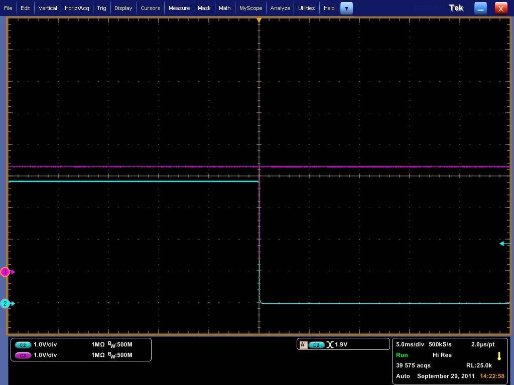
    Very important, I am only seeing Clk as constant line measuring at 3.3V. Attached is the Screen capture.

    Same goes for data.

    I am expecting Clock Pulses on the clock line, correct me if i am wrong.... which is not happening in my case.

    When i use the Step into function, i can see my I2C registers getting updated with desired values, but no activity on the scope. it just shows constant 3.3V.

    If i press the Run function, it sometimes takes the clock low and sometimes, i see no activity at all.  Ok, after trying several attempts, atleast it seems , its not pulling the clock low anymore...

    I have also attached the screen shot of ccs, with registers being watched. 

  • Rameez, looks like your I2C module is disabled. I2CMDR needs to be 6E20, IRS has to be set to 1 for the master to drive the bus clock.

  • Hello Vishal, by now u must have guessed my programming ability...

    Anyways... 

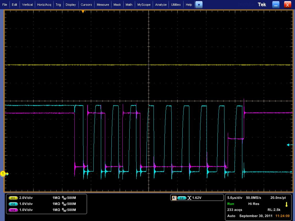
    As soon as my programs steps through the start bit (like earlier before), the clock goes low. Attached is the screen capture.

    I just changed the IRS bit to 1 as mentioned, no other changes..

  • Hello Vishal,

    After further digging in, i figured, even after setting the I2CMDR = 0x6E20, while stepping in to the code, it does not write it to the register... BB bit is set

    with I2CSTR = 0x1406. I dont know, how it is being set.???

  • Hello,

    After using the Step into function, i realized, once the code reaches the line to enable the STT bit, it does not get updated in the MDR register and it takes the clock line low with it. 

    Even if i set the MDR register as 0x6E20, it gets set as 0x4E20.


    I2caRegs.I2CSAR = 0x50;                      //Set slave address

               I2caRegs.I2CCNT = 2;                 //Set count to instr plus 2 address bytes

               I2caRegs.I2CDXR = 0xFF;           //Send Register Address          

     //       I2caRegs.I2CMDR.all = 0x6E20;   // Different approach..

               I2caRegs.I2CMDR.bit.TRX = 1;     //Set to Transmit mode

               I2caRegs.I2CMDR.bit.MST = 1;     //Set to Master mode

               I2caRegs.I2CMDR.bit.FREE = 1;    //Run in FREE mode

               I2caRegs.I2CMDR.bit.STP = 1;      //Stop when internal counter becomes 0

              I2caRegs.I2CMDR.bit.STT = 1;      //Send the start bit, transmission will follow. Once the step into function passes this step, i am expecting my MDR register value to update to 0x6E20 from 0x4E20. But here the value in the register remains at 0x4E20. 

                I2caRegs.I2CDXR = 0xEE;    // Send data.

    So, i have tried both approaches  .bit and .all. Both don't work. Any idea guys...

  • Ok,

    Here is another screen capture.... I can see only the Address being sent, and then the clock goes low..

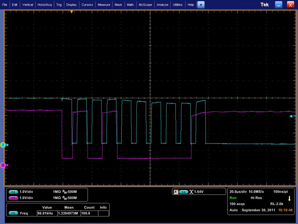
  • If you see the sequence you have (Start bit)S. (Address)1 0 1 0 0 0 0. 0(W).1(NACK...the value is neither gnd nor VCC its somewhere in the middle). It looks like your EEPROM is not acknowledging the address on the line. What EEPROM are you using?


  • I am using a ST M24C02.

  • Id suggest checking that the external pins E0->E2 on the EEPROM are properly grounded. other than that you could try transmitting at a lower speed @ 100k and see if that makes a difference. you can set CPSC to 5, CLKH to 30 and CLKL to 60. 


  • Hello Vishal,


    I tried using a lower clock speed of 100Khz... it still gives the same above waveforms.

    I tried using a lower pullup value of 2.2K instead of 3.3k. It still takes the clock low.

    I checked my address lines and they are properly grounded. I have hardware lines connecting to the ground. It seems something is not right with the piccolo device itself. I was planning to use the device in further applications.. 

  • Rameez,

    You can test the piccolo I2C module in loopback mode to see if its working or not. The following code snippet should help:  (you will have to setup gpio and clocks etc)

    Uint16 rx_byte;
    Uint16    PASS = 0;
    Uint16    FAIL = 1;

    // Initialize I2C
       I2caRegs.I2CSAR = 0x0050;        // Slave address - EEPROM control code

    //Setting up the I2C in digital loopback mode for 100KBps operation
        I2caRegs.I2CPSC.all = 5;   // Prescaler - need 7-12 Mhz on module clk (150/15 = 10MHz)

       I2caRegs.I2CCLKL = 60;            // NOTE: must be non zero
       I2caRegs.I2CCLKH = 30;            // NOTE: must be non zero

       I2caRegs.I2CIER.all = 0x00;        // Disable all interrupts
       I2caRegs.I2CMDR.all = 0x0020;    // Take I2C out of reset
                                           // Stop I2C when suspended
       I2caRegs.I2CFFTX.all = 0x6000;    // Enable FIFO mode and TXFIFO
       I2caRegs.I2CFFRX.all = 0x2040;    // Enable RXFIFO, clear RXFFINT,

       I2caRegs.I2CSAR = 0x50;            //This is not important in loopback mode
       I2caRegs.I2CCNT = 0x4;            //Sending two address bytes and two data bytes
      
       I2caRegs.I2CDXR = 0xFE;            //Load the target memory address high byte
       I2caRegs.I2CDXR = 0xAB;            //Load the target memory address low byte
       I2caRegs.I2CDXR = 0xAA;            //Data value 1
       I2caRegs.I2CDXR = 0x55;            //Data value 2
      
       I2caRegs.I2CMDR.all = 0x6E60;    //Set as master TX, start bit set, stop bit on end of tx,
                                           //Digital loopback mode
                                          
       while(I2caRegs.I2CFFTX.bit.TXFFINT == 0){}; //Loop till FIFO is empty


    while(I2caRegs.I2CFFRX.bit.RXFFST < 4){}; //Loop till receive FIFO has 4 words
                                                  //Give the RX enough time to receive all
                                                  //4 bytes


           rx_byte = I2caRegs.I2CDRR;
        if( rx_byte == 0x00FE ){
            FAIL = 0;
        }else{
            FAIL = 1;
        }
        rx_byte = I2caRegs.I2CDRR;
        if( rx_byte == 0x00AB ){
            FAIL = 0;
        }else{
            FAIL = 1;
        }
        rx_byte = I2caRegs.I2CDRR;
        if( rx_byte == 0x00AA ){
            FAIL = 0;
        }else{
            FAIL = 1;
        }
        rx_byte = I2caRegs.I2CDRR;
        if( rx_byte == 0x0055 ){
            FAIL = 0;
        }else{
            FAIL = 1;
        }
        DSP28x_usDelay(100000);
      /// at this point check value of FAIL in watch window
        PASS = 1;
    }


  • Hello Vishal,

    The value of FAIL=0

  • Hello Vishal,

    If, in your above code snipet, if i only change the value of I2CMDR register to 0x6E20 from 0x6E60, the same problem happens, my clock line goes low indefinitely on the 9th clock pulse.

  • If the loopback (0x6E60) mode works that means there is nothing wrong with the piccolo device. That would mean the slave is pulling the clock low. At this point I can only suggest switching out the EEPROM with a replacement and see if it still doesnt ACK the address.


  • Hello Vishal,

    The slave device EEPROM which i am using, is a production model device, its works fine if i read/write  with other i2c master like  NI -8451. 

    Again. i want to let you know, that i was able to successfully write to the EEPOM just once. But, when i tried the second time, it just did not work any more.

    Then i tried changing the pull up values, no effect.

    Then i figured, the piccolo uses 3.3V for i2c, whereas my EEPROM uses 5V for i2c. So i am now using a level shifter circuit, still no effect, apart from the i2c lines being pulled up to 5V now. 

    Now, i am feeling i am stuck at a dead end now. What suggestions do you have for the next steps if any. Is the code working fine for the write, i have attached it again.

    //I2C test 
    
    #include "DSP2803x_Device.h"     // DSP280x Headerfile Include File
    #include "DSP2803x_Examples.h"   // DSP280x Examples Include File
    
    // Prototype statements for functions found within this file.
    void   I2CA_Init(void);
    void main(void)
    {
       InitSysCtrl();            // Step 1. Initialize System Control:
       InitI2CGpio();            // Step 2. Initalize GPIO only for I2C functionality
       I2CA_Init();              // Step 4. Initialize all the Device Peripherals
                
               I2caRegs.I2CSAR = 0x50;          //Set slave address
               I2caRegs.I2CCNT = 2;             //Set count to data bytes pus address
               I2caRegs.I2CDXR = 0xFF;          //Send Register Address          
    //           I2caRegs.I2CMDR.all = 0x6E20;    // Set the full register.
               I2caRegs.I2CMDR.bit.TRX = 1;     //Set to Transmit mode
               I2caRegs.I2CMDR.bit.MST = 1;     //Set to Master mode
               I2caRegs.I2CMDR.bit.FREE = 1;    //Run in FREE mode
               I2caRegs.I2CMDR.bit.STP = 1;     //Stop when internal counter becomes 0
               I2caRegs.I2CMDR.bit.STT = 1;     //Send the start bit, transmission will follow 
                                                // My I2CSTR (status register) updates to 0x1406.
          					    // SCL goes low indefinitely.
               
    	   I2caRegs.I2CDXR = 0x00;        // Set data to be send.
               DELAY_US(10000);
            	
    }   // end of main
    
    
    void I2CA_Init(void)
    {
       I2caRegs.I2CSAR = 0x50;          // Slave address - EEPROM control code
       I2caRegs.I2CPSC.all = 5;         // Prescaler - need 7-12 Mhz on module clk for 60MHz CPU
       I2caRegs.I2CCLKL = 30;           // NOTE: must be non zero
       I2caRegs.I2CCLKH = 60;            // NOTE: must be non zero   
       I2caRegs.I2CIER.all = 0x24;      // Enable SCD,XRDY,RRDY,ARDY,NACK interrupts
       I2caRegs.I2CMDR.bit.IRS = 1;     // Take I2C out of reset, Stop I2C when suspended
       
       return;
    }
    
    //EOF

    Do you think, its the hardware causing the problems of the i2c lines?  

    One more important thing, when i do not connect the EEPROM at all, this is the waveform i get. 


  • Hello Vishal,

    Finally the Clock line pulling low problem has been solved.

    Thankfully i have the local TI support, who solved the problem. It was found on a particular pin 28(SDA). 

    After using a different SDA pin 32, it works like a charm.

    I appreciate all your help.

  • Hmm thats an interesting fix....In any case Im glad you were able to resolve this issue.

  • Hello Vishal,


    I am having some problems in reading more than 1 registers of the EEPROM.

    Here is the code i have adapted. Its only using 2 registers at this point, eventually i want to read 255 of them.

    addr[0] = 0x03;  //Register Address

    addr[1] = 0x04; //Register Address

    for (i = 0;i<2;i++) {


     while(I2caRegs.I2CSTR.bit.XRDY == 0){}; //Do nothing till data is shifted out

       I2caRegs.I2CSAR = 0x50; //Set slave address

       I2caRegs.I2CCNT = 1; //Set count to 1 address bytes

       I2caRegs.I2CDXR = addr[i]; //Send eeprom address            

       I2caRegs.I2CMDR.bit.TRX = 1; //Set to Transmit mode

       I2caRegs.I2CMDR.bit.MST = 1; //Set to Master mode

       I2caRegs.I2CMDR.bit.FREE = 1; //Run in FREE mode

       I2caRegs.I2CMDR.bit.STP = 0; //Dont release the bus after Tx

       I2caRegs.I2CMDR.bit.STT = 1; //Send the start bit, transmission will follow

     while(I2caRegs.I2CSTR.bit.XRDY == 0){}; //Do nothing till data is shifted out

       I2caRegs.I2CCNT = 1; //read 1 bytes from eeprom

       I2caRegs.I2CMDR.bit.TRX = 0; //Set to Recieve mode

       I2caRegs.I2CMDR.bit.MST = 1; //Set to Master mode

       I2caRegs.I2CMDR.bit.FREE = 1; //Run in FREE mode

       I2caRegs.I2CMDR.bit.STP = 1; //Stop when internal counter becomes 0

       I2caRegs.I2CMDR.bit.STT = 1; //Repeated start, Reception will follow

       rxdata[i] = I2caRegs.I2CDRR;


    } DELAY_US(1000); // end of for loop

    } // end of main

  • Ok, it now works, i had to check my RRDY status before reading the next byte.

    Thanks

  • Hello Vishal,

    I am trying tread from a micro. Right now, i m just reading 1 register.

    addr_mcu[0] = 0x02;

    for(j = 0; j < 1; j++) {

     while(I2caRegs.I2CSTR.bit.XRDY == 0){}; //Do nothing till data is shifted out

       I2caRegs.I2CSAR = 0x58; //Set slave address

       I2caRegs.I2CCNT = 2; //Set count to 2 address bytes

       I2caRegs.I2CDXR = addr_mcu[j];               //Send eeprom address 

       chk_sum[j] = 256 - ((addr_mcu[j] + 0xB0) % 256); //Calculate Checksum           

     while(I2caRegs.I2CSTR.bit.XRDY == 0){};        //Do nothing till data is shifted out    -- The program gets stuck at this line.. any ideas you have.

       I2caRegs.I2CDXR = chk_sum[j];                //Send Checksum

       I2caRegs.I2CMDR.bit.TRX = 1; //Set to Transmit mode

       I2caRegs.I2CMDR.bit.MST = 1; //Set to Master mode

       I2caRegs.I2CMDR.bit.FREE = 1; //Run in FREE mode

       I2caRegs.I2CMDR.bit.STP = 1; //Dont release the bus after Tx

       I2caRegs.I2CMDR.bit.STT = 1; //Send the start bit, transmission will follow

     while(I2caRegs.I2CSTR.bit.XRDY == 0){}; //Do nothing till data is shifted out

       I2caRegs.I2CCNT = 3; //read 3 bytes from eeprom

       I2caRegs.I2CMDR.bit.TRX = 0; //Set to Recieve mode

       I2caRegs.I2CMDR.bit.MST = 1; //Set to Master mode

       I2caRegs.I2CMDR.bit.FREE = 1; //Run in FREE mode

       I2caRegs.I2CMDR.bit.STP = 1; //Stop when internal counter becomes 0

       I2caRegs.I2CMDR.bit.STT = 1; //Repeated start, Reception will follow

     while(I2caRegs.I2CSTR.bit.RRDY == 0){}; //Do nothing till data is shifted out   

       for(k = 0; k < 3;k++) {

        while(I2caRegs.I2CSTR.bit.RRDY == 0){}; 

    rxdata_mcu[k] = I2caRegs.I2CDRR;

        } //End of recieve for loop

       DELAY_US(100);                               //Delay required for next register to read

    }   // End of for loop

    } // end of main

  • Hi Rameez, Is the eeprom address being shifted out on the SDA line and are you getting an ack?

  • Yes,

    EEPROM address, i am getting an ack.

  • Hmm looks like you are writing to the I2CDXR register, polling the XRDY bit,  then writing to I2CMDR.

    Writing to I2CDXR clears XRDY, which you then poll. It will continue to sit in the loop as the mode register hasnt been configured to shift those bits out onto the line.

    Write to I2CMDR, then DXR and then poll. I cant think of another reason why the module wont shift the bits out onto the line.

  • Ok, 

    Understood.

    Initially, i was not polling the XRDY bit. 

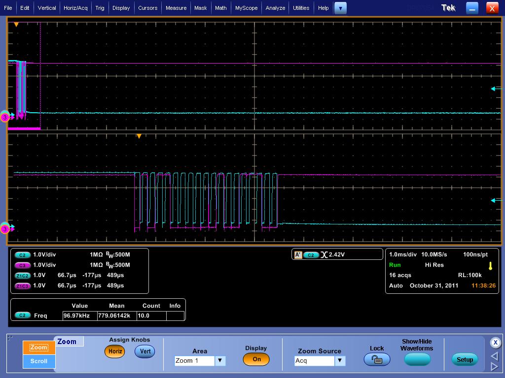
    In that case, instead of sending my 2 bytes (since count =2) address and checksum, it was just sending checkum. Attached is the scope capture.

    Cant i just write to the DXR register as follows

    I2caRegs.I2CDXR = addr_mcu[j];

    I2caRegs.I2CDXR = chk_sum[j];

    If yes, how can i check to see if content in DXR is shifted before i am filling it with 2nd byte (checksum in this case).

    From the scope capture, i can see my ACk from the EEPROM, and my 2nd byte (checksum). But, the register address (0x02 in this case) , i think is overwritten in the DXR.

  • If you want to write successive bytes to I2CDXR you need to be in FIFO mode while transmitting. If not you will have to poll XRDY each time to figure out when to write the next byte to DXR

  • Ok,


    Now it works. i am not using FIFO at this time, but something to consider.

    I just changed my checksum byte to write to DXR after the MDR register as you suggested.

    I appreciate your help.

  • Hi friend ,

    I have return eeprom interface with c2000  TMS320F28027 through i2c . I have problem in read and write please any one help me

    this is my code...

        while(I2caRegs.I2CSTR.bit.XRDY == 0){};
        I2caRegs.I2CDXR = *txBuf_pu8;

    }

    void i2cRead(Uint16 memAddr_u16, unsigned char *rxBuf_pu8, Uint32 rxDataLen_u32)
    {
        Uint32 i = 0;
        I2caRegs.I2CSAR = I2C_SLAVE_ADDR;             //Set slave address
        I2caRegs.I2CCNT = 2;                         //Set count to 2 address bytes
        I2caRegs.I2CDXR =((memAddr_u16 >> 8) & 0xFF);            //Send eeprom high address
        I2caRegs.I2CMDR.bit.TRX = 1;                 //Set to Transmit mode
        I2caRegs.I2CMDR.bit.MST = 1;                 //Set to Master mode
        I2caRegs.I2CMDR.bit.FREE = 1;                //Run in FREE mode
        I2caRegs.I2CMDR.bit.STP = 0;                 //Dont release the bus after Tx
        I2caRegs.I2CMDR.bit.STT = 1;                 //Send the start bit, transmission will follow
        
        while(I2caRegs.I2CSTR.bit.XRDY == 0){};         //Do nothing till data is shifted out
        I2caRegs.I2CDXR = ( memAddr_u16 & 0xFF );              //Send eeprom low address
        I2caRegs.I2CCNT = rxDataLen_u32;                //read 5 bytes from eeprom
        I2caRegs.I2CMDR.bit.TRX = 0;                 //Set to Recieve mode
        I2caRegs.I2CMDR.bit.MST = 1;                 //Set to Master mode
        I2caRegs.I2CMDR.bit.FREE = 1;                //Run in FREE mode
        I2caRegs.I2CMDR.bit.STP = 1;                 //Stop when internal counter becomes 0
        I2caRegs.I2CMDR.bit.STT = 1; //Repeated start, Reception will follow
        for(i = 0; i < rxDataLen_u32; i++)
        
            while(I2caRegs.I2CSTR.bit.RRDY == 0){};     //I2CDRR not ready to read?
            *rxBuf_pu8 = I2caRegs.I2CDRR;
            rxBuf_pu8++;
        }
    }


    void main(void)
    {
           Uint16 address = 0x0005;
           unsigned char txdata = 'H';
           unsigned char rxdata = 0;

           InitSysCtrl();
           InitI2CGpio();
           DINT;
           InitPieCtrl();
           IER = 0x0000;
           IFR = 0x0000;
           InitPieVectTable();
           i2cInit();
           EINT;

           i2cWrite( address, &txdata, 1);

           while(1)
           {
               i2cRead( address, &rxdata, 1);
           }
    }