This thread has been locked.

If you have a related question, please click the "Ask a related question" button in the top right corner. The newly created question will be automatically linked to this question.

Bq34z100 Control and Block commands

Other Parts Discussed in Thread: BQ34Z100, BQ34Z100EVM, INA219, BQ34Z110, BQEVSW, EV2400

Hi ,

I wanted to know about how control command and its subsequent 2byte sub commands retrieve data.

We are considering a code  to send command 1 byte at a time to fetch the data.

So if suppose i want to fetch 'Instantaneous Current' (measured by the gauge),  send totally 4 bytes of command byte by byte in a row?

If so, i ll have to send bytes 0x00 and 0x01( control - command pair) and then send sub command (0x0018 for current)  0x00  first is used to retrieve the least significant byte of current and command 0x18 next  is used to retrieve the most significant byte.. Is that how it is?

Also, it would be great if u could tell me how available block commands ( Device Name, Manufacturer name, Device Chemistry) retrieve data.

Please help me with clarity on these as soon as possible, i am running out of time. 

Regards and Thanks,

Shamanth D R

  • Shamanth

    We are working on a response to your inquiry.

    Regards

    Tom

  • OK thank you, ill be waiting for your response.

    Regards, 

    Sham

  • Sham,

    READING SUBCOMMANDS IN bq34Z100

    Here is how you can read the instantaneous current. Its a four step process - two byte writes, followed by two byte reads. In I2C, it all comes down to bytes.

    1. Send the least significant subcommand byte to location 0. For example:

    lerror = I2C_Write_Byte (0, 0x18, 0xAA)  // Where first arg is the address, second is the data, third is the device address.

    2. Send the most significant subcommand byte to location 1:

    lerror = I2C_Write_Byte (1, 0, 0xAA)

    3. Read the least significant byte of the response:

    lerror = I2C_Read_Byte (0, yLS, 0xAA)  // yLS is the least significant byte of the returned current in mA.

    4. Read the most significant byte of the response:

    lerror = I2C_Read_Byte (1, yMS, 0xAA)  //  Note that the result is a bipolar two's complement number.

    Using a different order of operation can cause erroneous results.

    Regards,

    Doug & Tom

  • Thank you Doug & Tom,

    1. In the 3rd and 4th step above, the third argument of I2C_Read_Byte( ) is supposed to be 0xAB if i am not wrong? Because the BQ34Z100 data sheet (Pg 28) says device address is 0xAA for write and 0xAA for read.

    2. what location does the first argument (0 or 1) in each step address to? Is it the register internal to the I2C communication engine or some location inside BQ?

    3. Can we avoid using the first argument 0 or 1 if v consider I2C burst send (sending continuously control command followed by sub command in the following manner : 0x00 -> 0x01-> 0x18 -> 0x00 ) and burst receive? 

    Regards,

    Sham

  • It is absolutly frustrating. Even best equipped with EVM and I2C-to-USB Interface I am struggling find out how subcommands work... the datasheet is just not precise enough!

    Can someone please explain ON BIT LEVEL what exactly has to be sent on the bus?

    Let's please just read out the

    DEVICE_TYPE (Control Data 0001) for example.


    I managed to let the LEDs light up, but I don't understand why it would work. Really sucks when your close in time in your project.

    Here the samplecode that lights the LED.

     Buffer_Tx1[0] = 0x00;  

    Buffer_Tx1[1] = 0x30;    

    Buffer_Tx1[2] = 0x00;  

    I2C_Master_BufferWrite(Buffer_Tx1, 3, 0xAA);


    Thans and best regards.

    Tobias


  • I found this frustrating myself.  But I do have it working finally.

    I am doing a burst write of two bytes then burst read of two bytes.

    I believe some important details I learned would be:

    1. 2 byte commands must be sent (not abbreviating by just sending the LSB)

    2. A delay of approx 40 us must be present between the write and read.

    3. The read command must reset the I2C address pointer (ie, use incremental read protocol from data sheet instead of quick read).


    These are just my observations and it'd be nice if a TI rep could confirm these statements...

  • We have now built the first prototypes of the BMS, but we are still not able to read the subchannel. If TI does not support imediatelly I'll kick the gasgauge of the desgin and look for another solution. Never seen such a frustrating interface in combination with poor manual and support. absolutly annoying!

    Can someone please provide a byte by byte, step by step, explenation of what to do?


    THANK YOU

  • a screenshot from an oszillicope would be extremly helpfull! THANK YOU

  • Tobias,

     I should be able to send you some information in the morning.

    Regards

    Tom

  • Tobias,

    I tried a couple of Control() Subcommands and checked the waveforms on an oscilloscope. I tried the "Write I2C Data Block" and the "Read/Write I2C Byte" methods.

    Example 1:

    DEVICE_TYPE  Control() Subcommand 0001 and the correct answer is 0100 for the bq34z100.

    Using  "Write I2C Data Block"

    enter    I2CCommand 00  Data Block  0100   press    Write Data button                           (The scope waveforms occur in this order. AA, 00, 01, 00)

    Using "Read I2C Data Block"

    enter    I2CCommand 00  Read Data Size  2   press    Read Data button                           (The scope waveforms occur in this order. AA, 00, AB, 00, 01)

    The GUI returns 0001, which is Little Endian for 0100. This is the DEVICE_TYPE for the bq34z100.

    Using "Read/Write I2C Byte"

    enter    I2CCommand 00  Byte  01   press    Write Byte button                              (The scope waveforms occur in this order. AA, 00, 01)

    enter    I2CCommand 01  Byte  00   press    Write Byte button                              (The scope waveforms occur in this order. AA, 01, 00)

    enter    I2CCommand 00   press    Read Byte button; GUI returns a 00                (The scope waveforms occur in this order. AA, 00, AB, 00)

    enter    I2CCommand 01   press    Read Byte button; GUI returns a 01                (The scope waveforms occur in this order. AA, 01, AB, 01)

    The correlates to 0001, which is Little Endian for 0100.

    Example 2:

    CHEM_ID  Control() Subcommand 0008 and the correct answer is 0107 for the default bq34z100.ChemID.

    Using  "Write I2C Data Block"

    enter    I2CCommand 00  Data Block  0800   press    Write Data button                           (The scope waveforms occur in this order. AA, 00, 08, 00)

    Using  "Read I2C Data Block"

    enter    I2CCommand 00  Read Data Size  2   press    Read Data button                           (The scope waveforms occur in this order. AA, 00, AB, 07, 01)

    The GUI returns 0701, which is Little Endian for 0107. This is the default ChemID for the bq34z100.

    Using "Read/Write I2C Byte"

    enter    I2CCommand 00  Byte  08   press    Write Byte button                              (The scope waveforms occur in this order. AA, 00, 08)

    enter    I2CCommand 01  Byte  00   press    Write Byte button                              (The scope waveforms occur in this order. AA, 01, 00)

    enter    I2CCommand 00   press    Read Byte button; GUI returns a 07                (The scope waveforms occur in this order. AA, 00, AB, 07)

    enter    I2CCommand 01   press    Read Byte button; GUI returns a 01                (The scope waveforms occur in this order. AA, 01, AB, 01)

    The correlates to 0701, which is Little Endian for 0107.

    I hope that this helps.

    Tom

  • Tom,

    thank you so much! I finally got it working!

    best regards,

    Tobias

  • Hi,

    I have used your istruction about Read process with Control() command and Subcommand()

    and all work correctly , but I have some problems regarding write procedure for example with command :

    Controll() with subcommand SET_FULLSLEEP (0x0010)

    could you show me the correct commands I have to send ?

    Thanks in advance (sorry for my English)

    Giuliano

  • Giuliano,

    I posted a couple examples using subcommands at this e2e location. Please review it and see if it helps.

    http://e2e.ti.com/support/power_management/battery_management/f/180/p/213060/820268.aspx#820268

    Tom

  • Thanks Tom ,

    if i want to use Controll() with subcommand SET_FULLSLEEP (0x0010) i have to send

    AA, 00, 01, 00 . Correct ?

    Thanks again

    Giuliano

  • The SET_FULLSLEEP subcommand is 0x0010, so the I2C byte order will be AA, 00, 10, 00

  • Has anyone managed to get this process working with Arduino's Wire interface? I seem to be calling all the data commands except Control() accurately. For instance, to get Voltage() I use:

    DEVICE_ADDRESS = 85;

    Wire.beginTransmission(DEVICE_ADDRESS);

    Wire.write(0x08);

    Wire.write(0x09);

    int transmitResult = Wire.endTransmission();

    Wire.requestFrom(DEVICE_ADDRESS, 2);
    int availableBytes = Wire.available();

    int result = 0;
    if (availableBytes > 0){

    for (int i = 0; i < availableBytes; i++){
    result = result << 8 | Wire.read();
    }
    }

    Nothing similar to this works for Control(). 

  • Chidube,

    Are you referring to the Control() Subcommands on the bq34z1xx devices? If so, I have an e2e posting that goes through a couple of examples as to how to use them.

    http://e2e.ti.com/support/power_management/battery_management/f/180/p/213060/820268.aspx#820268

    Regards
    Tom

  • Ok, i have already try the command and all work properly

    thank you

  • Hello a
    I'm using files for Arduino,from

    http://www.pcbheaven.net/forum/index.php?topic=1727.15

     this post, and receiving this respond form the bq34z100,


    Shell start
    -> VOLT
     > Voltage
    328
    -> TEMP
     > Temperature
    3002
    -> FW_VERSION
     > FW Version
    0x6
    -> CURRENT
     > Current
    0
    -> CURRENT 
    > Current
    64116
    ->


    the voltage on my voltmeter is 7.8v,here i'm receing 328,

    and the Temperature in the room is 21C / 70F,i'm receiving 3002
    there is any way you can tell me, what I can do to receive the actual value (7.8v),
    i'm using bq34z100EVM module for my test,
    Thank you.

  • Hamayak,

    You should check your calibration. The voltage will read out in hex and will be in milli-volts after converting to decimal. Don't forget to swapped the bytes that are read out. e.g. If you read B61C for voltage, then you will convert 1CB6 to decimal. (7350mV) Temperature will read out in hex and will be in 0.1 degK after converting to decimal. The byte swap applies here as well.

    Tom

  • Dear Tom

    I am confused sorry about the last post

    in my understanding to write the Control() command which is 00/ 01 and the SET_FULLSLEEP subcommand is(0x0010)

    Then my micro should send

    AA 00 01 10 00

    Which is Write AA ,2 byte command 00 and 01 ,sub command 10 00 litte Endian

    Please help I am lost

    Best Regards

    Peter 

    I appologize I have selected the wrong post to post my question I am very soryr this happend

  • Hey Giuliano is there any way you would share the working Arduino code for the Bq34z100 fuel gauge? I'm really needing it and can't find any good code for Arduino anywhere. Any help is appreciated. 

  • Hey Tobias, I see you have the Bq34z100 working with Arduino and I'm really wanting to do the same thing. I'm wondering if you could share the working Arduino code with me. You can email me at Sales@PortableSolarPower.Biz if so. I'm willing to pay for it. 

  • OK it looks like the info I need is here to get the Instantaneous Current reading pulled from the Command() routine but I need some help modifying my Aruduino code to get this last bit of data pulled from the Bq34z100. 

    Here is the code we tried to use to pull Instantaneous Current but its now working. Can you see anything that is wrong that needs to be changed to get it to work correctly? 

    void readInstCurrent()
    {
      // Write Control command bytes to gas gauge chip: 0x00/0x01
      Wire.beginTransmission(BQ34Z100);
      Wire.write(0x00);
      Wire.endTransmission();
      
      Wire.beginTransmission(BQ34Z100);
      Wire.write(0x18);
      Wire.endTransmission();
      
      Wire.beginTransmission(BQ34Z100);
      Wire.write(0x01);
      Wire.endTransmission();
      
      Wire.beginTransmission(BQ34Z100);
      Wire.write(0x00);
      Wire.endTransmission();
      
      Wire.requestFrom(BQ34Z100,1);
      inst_current_lsb = Wire.read();
     
      Wire.requestFrom(BQ34Z100,1);
      inst_current_msb = Wire.read();
      
      unsigned int temp = inst_current_msb << 8;
      
      inst_current = temp + inst_current_lsb;
    }
     
    I have all the standard commands up and working using the code layout below. 
     
    void readAverageCurrent()
    {
      Wire.beginTransmission(BQ34Z100);
      Wire.write(0x0a);
      Wire.endTransmission();
      
      Wire.requestFrom(BQ34Z100,1);
      
      unsigned int low = Wire.read();
      
      Wire.beginTransmission(BQ34Z100);
      Wire.write(0x0b);
      Wire.endTransmission();
      
      Wire.requestFrom(BQ34Z100,1);
      
      unsigned int high = Wire.read();
      
      unsigned int high1 = high<<8;
      
      avg_current = high1 + low;
    }
  • Ryan,

    The flow looks like it follows the command sequence to read the Current. You may have to compare the I2C waveforms for each of your commands to the commands in the Read/Write I2C Byte example that I provided in this e2e posting.

    http://e2e.ti.com/support/power_management/battery_management/f/180/p/213060/820268.aspx#820268

    Tom

  • Thomas do you have a Arduino that you could run my code on at work and see if you can get the Instantinous Current reading to work based on your testing? I'm not smart enough to figure it out but I was able to get all the above to show up correctly. 

    Battery State of Charge: 17%
    Remaining Capacity: 1.68 Ah
    Battery Pack Voltage: 3.34 V
    Average Current Draw: 3.77 A
    Battery Temperature: 78.80 F
    Power Input/-Output: 12.59 W
    Time Till Empty: 1092.25 Hours
    Time Till Full: 3.52Hours
    Standby Time Till Empty: 8Days
    Battery Cycles: 8
    Battery Health Percentage: 100
    100% Charged Capacity : 10.32 Ah
    Standby Current Consumption : -8mA
    Avaliable Energy : 4.89 Wh
    Average Discharge Power : -0.53 W
    PassedCharge : -1.47 Ah
    SelfDischargeCurrent : 2 mAh
    Flags : 256
    Full Charge Capacity : 10.32 Ah
    Chip Temperature : 82.40 F

    I can email you the Arduino Code so you can try it on your end, it should be easy for you get going. The communication is working for everything else so I figure its probably an easy quick fix if you understand what your looking at. 

    Let me know. 

  • Ryan,

    I have not used an Arduino setup before. These parameters that you have read successfully are either SMB commands or Extended SMB commands. Current is a Control Subcommand, so its structure is a little different. Do you receive any data when you try reading the Current parameter?

    Tom

  • Thomas I do get a single number 3 reading back when I use the following code below to try to access the Instantaneous Current reading. 

    Something is not right but it can't be to difficult to figure out since everything else is working. 

    Here is the actual code that I am working with that another member supplied. 

    ---------------------------------------------------------------------------------------------------

    #include <Wire.h>                                                                          // Wire library for communicating over I2C
    #define BQ34Z100 0x55                                                                      // This is the I2C address of the BQ34Z100
         
    
    byte instCurrentLSB[] = {0x00, 0x18};
    byte instCurrentMSB[] = {0x01, 0x00};
    unsigned int inst_current_lsb, inst_current_msb  ;
    int inst_current, avg_current ;
    
    // ~~BQ34Z100 Status Functions~~
    
    
    void readAverageCurrent()
    {
      Wire.beginTransmission(BQ34Z100);
      Wire.write(0x0a);
      Wire.endTransmission();
      
      Wire.requestFrom(BQ34Z100,1);
      
      unsigned int low = Wire.read();
      
      Wire.beginTransmission(BQ34Z100);
      Wire.write(0x0b);
      Wire.endTransmission();
      
      Wire.requestFrom(BQ34Z100,1);
      
      unsigned int high = Wire.read();
      
      unsigned int high1 = high<<8;
      
      avg_current = high1 + low;
    }
    
    void readInstCurrent()
    {
      // Write Control command bytes to gas gauge chip: 0x00/0x01
      Wire.beginTransmission(BQ34Z100);
      Wire.write(0x00);
      Wire.endTransmission();
      
      Wire.beginTransmission(BQ34Z100);
      Wire.write(0x18);
      Wire.endTransmission();
      
      Wire.beginTransmission(BQ34Z100);
      Wire.write(0x01);
      Wire.endTransmission();
      
      Wire.beginTransmission(BQ34Z100);
      Wire.write(0x00);
      Wire.endTransmission();
      
      Wire.requestFrom(BQ34Z100,1);
      inst_current_lsb = Wire.read();
     
      Wire.requestFrom(BQ34Z100,1);
      inst_current_msb = Wire.read();
      
      unsigned int temp = inst_current_msb << 8;
      
      inst_current = temp + inst_current_lsb;
    }


    void setup()
    {
      Serial.begin(9600);
    
      Wire.begin();
    }
    
    void loop()
    {
    
     readAverageCurrent();
     Serial.print("Average Current Draw: ");
     Serial.print(avg_current);
     Serial.println(" mA");
     
     readInstCurrent();
     Serial.print("Instantaneous Current Draw: ");
     Serial.println(inst_current);
     
     Serial.print("Instantaneous Current Draw LSB: ");
     Serial.println(inst_current_lsb);
     
     Serial.print("Instantantous Current MSB: ");
     Serial.println(inst_current_msb);
     
     Serial.print("\r\n");
      
     delay(1000);
    }

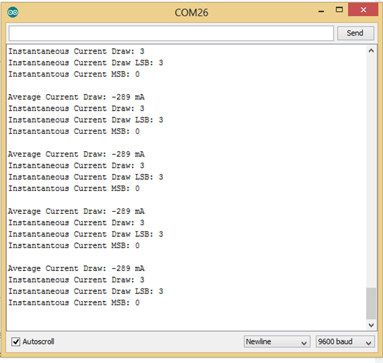
    With the code above I get the following serial output:

    In the datasheet it says the Control() subcommand for Instantenous Current is 0x0018 . I only see 0x18 above in the void readInstCurrent() block, I tried changing that to 0x0018 but it made no difference. 

  • Ryan,

    I think that that problem may be that you have to read MAC address 00 and MAC address 01 for Control Subcommands. You just had one read statement when reading the Average Current, but this is an SMB parameter and the device supports auto-increment with SMB parameters. It does in support auto-increment with the "Read/Write I2C Byte" feature. Maybe you can use two reads or trying implementing the "Read I2C Data Block" feature that will read more than one byte of data. 

    Tom

  • Thanks for the info Tom, thats all beyond my current programming capabilities right now. 

    Is there anyway you could alter the code I provided how you think it should be so I can give it a try and report back? 

    I'll send ya Gift Card for a nice $100 dinner if you help me figure it out. 

  • Rayn

    I wish that I could be more help, but I would have to experiment with the Arduino device as well to modify the commands. If I were to hazard a guess, then I would try reading two bytes and see if this emulates our block read command.

          Wire.requestFrom(BQ34Z100,2);

           inst_current_lsb = Wire.read();

    Maybe someone else on the forum can take you up on the $100 support opportunity.

    Good luck,

    Tom

  • Your recommendation did make a difference. 

    Here is the code I changed. Should I add the Wire.requestFrom(BQ34Z100,2); to both wire request or just the 1st one?

    void readInstCurrent()
    {
      // Write Control command bytes to gas gauge chip: 0x00/0x01
      Wire.beginTransmission(BQ34Z100);
      Wire.write(0x00);
      Wire.endTransmission();
      
      Wire.beginTransmission(BQ34Z100);
      Wire.write(0x18);
      Wire.endTransmission();
      
      Wire.beginTransmission(BQ34Z100);
      Wire.write(0x01);
      Wire.endTransmission();
      
      Wire.beginTransmission(BQ34Z100);
      Wire.write(0x00);
      Wire.endTransmission();
      
      Wire.requestFrom(BQ34Z100,2);
      inst_current_lsb = Wire.read();
     
      Wire.requestFrom(BQ34Z100,1);
      inst_current_msb = Wire.read();
      
      unsigned int temp = inst_current_msb << 8;
      
      inst_current = temp + inst_current_lsb;
    }
    

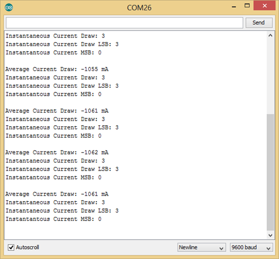
    Here is the serial output from the Instantaneous Current reading now: 

    Looks like were making progress. 


  • How much current do you expect? I would think that only one read statement would be required, if you are reading two bytes of data.

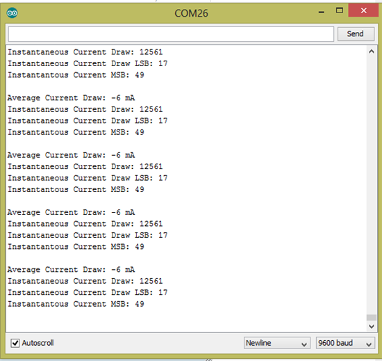
  • Its has a constant current draw right now of 6 mA so the current should be matching that. 

    About the Read Statement, are you saying that I should eliminate the 2nd read statement below?

    Wire.requestFrom(BQ34Z100,2);
    inst_current_lsb = Wire.read();

    Wire.requestFrom(BQ34Z100,1);
    inst_current_msb = Wire.read();

    Also what format is the Instantaneous Current reading in? mA? The data sheet does not say.  I'm assuming its a signed int. 

  • Yes, I would eliminate the second set of commands. Current should be returned as a signed integer. Maybe the CC Offset and full scale current have not been calibrated yet, so the reading is not accurate.

  • Hey Tom, I can send you a free Arduino Micro board for you to work with. I can send you the wiring instructions also, Its just ground, SDA, and SCL for I2C communication so its really easy to hook up. Just let me know where to send it to. 

    I never did get the Instantaneous Current reading working but I know were very close. 

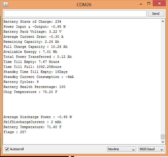
    Now for the Flags status reading I'm getting numbers  back like : 257 and sometimes 4 digit numbers. See the FLAGS: line in the image below:

    What format should the Flag Status readings be in? How do I make sense of the 257, the user guide for the chip does not mention anything about this. Please help me understand how the FLAG status info can be used. 

    I would like to be able to read the sleep state status of the Bq34z100 chip so I can trigger my Microcontroller to sleep also when the chip goes into deep sleep if possible. 

  • Ryan,

    Thanks for the offer, but I seriously doubt that I will have the time to work wit the Arduino setup to debug this issue.

    Data is read from the device byte swapped, so if bits are defined as Bit15, Bit14, ...., Bit0, then it will be read out as

    Bit 7, Bit 6, ...Bit 0, Bit 15, Bit14, .... Bit 8

    You cannot read status in FullSleep, because it would cause it to come out of FullSleep mode.

    Tom

  • Hey Thomas I figured out how to get the Instant current reading by using the Average Power data that does provide live wattage readings. So I simply divided wattage by voltage which gives me instant current readings. Problem Solved!

    Now how do I go about using the demo board for the Bq34z100 with battery packs above 3v? 

    I want to use it with a 12.8v , 4 cell LFP battery pack. Isn't there a resistor value I need to calculate and add to the demo board? 

    I'm not good with calculating the values so if you could just tell me what I need and where to put it I'll get it done. 

    Thanks!

  • Ryan

    LiFePO4 cells charge to 3.6V, so 12.8V seems low for a 4S configuration. You can use the formula on page 26 of the datasheet to calculate the resistor divider values.

    Rseries = 16500 Ω (Vin max mV – 900 mV) / 900 mV

    Regards

    Tom

  • Yes the nominal 4 cell voltage is 3.2v x4 = 12.8v , and the charged voltage is 3.6 x4 = 14.2v. 

    Based on the info above can you tell me what I need to do to get the demo board setup to work correctly with the 4 cell 14.2v battery pack? 

    Where do these resistors go on the demo board? 

  • You can just set the J2 jumper to 16V and the J5 jumpers to Multicell. If you want to fine tune the resistor divider to 14.2V, then you can change R1 to a 249 kohm resistor.

  • Thank you very much Tom! 

    I'll use the 249k resistor since thats what I will be using in the final circuit design. 

    I'm finally got this thing up and running now. 

    The only thing left is learning what the FLAG codes are referring to. I just have to guess what code means what. 

    Here are the Flags I have seen so far:

    Flag  = 1

    Flag  = 262

    Flag  = 263

    Flag  = 384

    Flag  = 4358

    Flag  = 2048

    Flag  = 34816

    Flag  = 256

    Flag  = 257

    Flag  = 640

    Flag  = 512

    Any ideas on how to decipher these codes into something usable? 

  • Ryan,

    Can you please provide your code for the following screen?

    Thanks.

  • https://github.com/samuelvanderwaal/bq34z100

  • It took me weeks to find that code. 

  • I know,i'm following this forum last 2 weeks.

    now,I want to figure, how measure

    Battery Pack Voltage:

    For test I'm using 12v power supply  

  • Do you have an Arduino Board? You need one to communicate with the Bq34z100 chip via I2c. 

    Once you have those hooked up you need to run the code I gave you the link to and then open the serial output terminal in Arduino IDE and that will open a window that you see in the screenshots in my post. 

  • I have that, and almost everything is working perfect, only the voltage reads 3.2v

    instead of 12v

  • Do you have the multi cell jumpers setup right on the Bq34z100 evaluation board? 

    Is the current reading working?