Because of the Thanksgiving holiday in the U.S., TI E2E™ design support forum responses may be delayed from November 25 through December 2. Thank you for your patience.

This thread has been locked.

If you have a related question, please click the "Ask a related question" button in the top right corner. The newly created question will be automatically linked to this question.

Question about TL431 application "High-Current Shunt Regulator"

Other Parts Discussed in Thread: TL431

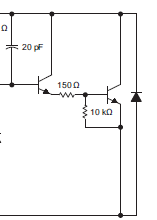
In my application, I will use a PNP to sink 4A current based on above configuration from page 29 of TL431 datsheet.


My question is when the Ic current of PNP collector is around 4A the Ib current of PNP base is around 200mA.


How the TL431 is going to sink that 200mA base current?


Many thanks for your answer.


  • Hello,

    To prevent damage to the TL431 you should keep the current into the cathode to at most 100mA, the absolute maximum it can take is 150mA but at this level it's proper operation is not guaranteed. As such it would be recommended you reduce the current entering the device.

    Regards,

    Robert Regojo.

  • David,

    If you replace the PNP with a Darlington PNP transistor, the increased transistor gain will lower the base current required.

    Regards,
    Ron Michallick


  • Please excuse me for jumping in on this thread.

    I am looking for a shunt to limit back-emf on a 24V supply that is powering a 24V 60W Brushless motor. According to the motor datasheet, the motor can produce up to 60V during rapid deceleration. The circuit with PNP transistor in the above post looks suitable except the 60V spike is outside the limits for a TL431. Could somebody please advise if there is a way of increasing the max voltage for this circuit, and if it would be suitable for my project?

    Regards

    John

  • John,

    If the clamp is successful then the voltage will not exceed the maximum 36V of the TL431.
    If the voltage on the clamp exceeds 36V, that means the clamp is not powerful enough to do the job.

  • Hi Ronald,

    Many thanks for your prompt reply. Could you elaborate on 'powerful enough' please?

    Does this refer to switching the PNP on hard enough to not be in the linear region, or choice of resistor divider values to switch the TL431 quick enough?

    Thanks again

    John

  • John,

    The 'power' comes from the PNP being to sink all the current that the motor provides during the clamp time.
    The rising voltage of the cathode helps the reaction time due to the internal capacitance seen here. 

    Cathode is top node and anode is bottom node.