This thread has been locked.

If you have a related question, please click the "Ask a related question" button in the top right corner. The newly created question will be automatically linked to this question.

LP3878-ADJ: Which is the on/off threshold value for SHDN?

Other Parts Discussed in Thread: BQ24030, LP3878-ADJ, LP3878, MSP430F5437, BQ24032A

Hi all,

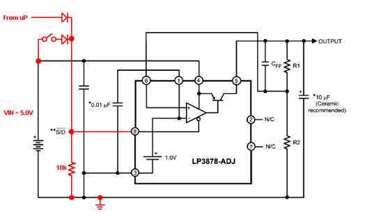
I'm powering an MSP430 project from batteries through a bq24030, having an input voltage to my system (out of the bq24030) between 3.7v and 5v, thus I'm inserting the LP3878-ADJ as a regulator down to 3.3v for the whole system.

On the functional side, I have to be able to send a shutdown command to the display before the system is turned off:

- my first approach was to monitor the SVS interrupts for sending the command as soon as the voltage drops, but I don't think it is feasible. Maybe using a capacitor? If any of you can help me with this approach I would highly appreciated.

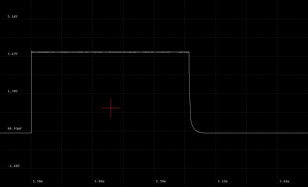
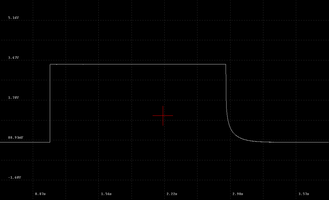
- as that approach didn't seem to work I'm trying to implement a soft power switch, which allows me to shutdown the system from the uC and turn it on from a push button. For doing this I'm relaying in the shutdown (~SHDN) pin of the LP3878. When using the push button I feed Vin = 5V into SHDN, and I want the uC to take over that pulling up once it has booted, but it seems that the 3.3v I've got in the system are not enough to keep SHDN high. I've been reading the datasheet and it seems that the ON threshold is 1.4v when Vin=3v and Vout=1v, but it says nothing about what is the relation of this voltages with the SHDN on and off thresholds. I've found, empirically that a voltage of 3.7v holds the SHDN high and thus powers the system. Can you help me finding that threshold?

- Finally, in my desperation, I've tried to make it work driving a transistor, but didn't managed either. I only have a couple of npn transistors at hand, and I think I should be using pnp for this. Am I right?

As a side note, my project is a portable equipment, so battery conservation is highly relevant. Do you think the 1st approach with a mechanical OFF slider button would be much better (less consumption) than the shutdown of the regulator? (I think I've read the regulator only draws 10uA when in shutdown.)

Thanks a lot for any help or light you can through, best regards,

Asier.

  • " ... a voltage of 3.7v holds the SHDN high ..." is not even close to being correct.

    The typical LP3878-ADJ output VS/D On/Off threshold voltage is closer to ~1.4V ... at the /SHUTDOWN pin. If you are pulling the /SHUTDOWN pin high through a resistor you will need to allow for I*R voltage drop with a pin current of 5uA to 15uA

    I'm not aware of any sensitivity of the VS/D threshold to the input voltage, or the output voltage, but I can check this on the bench this afternoon.

    As for the input current when 'OFF', there are two VS/D specifications : 1) to get input current down to 10 micro-A, or less, you must drive the /SHUTDOWN pin down to 40 milli-V, or less. 2) if you drive the /SHUTDOWN pin to 600mV or less, the input current will typically be less than 50 micro-A. Note that even though these two specifications are called VS/D, they are NOT related to the output being OFF, they are related only to the input pin current. The 'output off' threshold with VS/D falling is typically around 1.3V.


  • Hi Donald,

    Thanks a lot for your fast answer.

    While I understand some bits that points me to think that I will be able to build the circuit, I'm afraid I'm too much of an apprentice in electronics to fully follow your explanation. I'm more a software guy.

    Could you please elaborate a bit more?

    When you say "output VS/D On/Off threshold voltage is closer to ~1.4V", do you mean /SHUTDOWN is also an output?

    I'm connecting Vin (5V) to the /SHUTDOWN pin through a push button and a diode, then the /SHUTDOWN pin to ground through a 10k resistor, and also the output from the uC through a diode to the /SHUTDOWN pin. Well, to be honest, so far I haven't connected the uC but I'm rather manually pushing Vcc (3.3v) as if the uC where rising the GPIO, for simulation.

    Thanks a lot for your help,

    Asier.

  • The /SHUTDOWN pin is an input only.

    When the voltage on the /SHUTDOWN pin is greater than ~1.4V the output will be enabled (i.e. ON).

    When the voltage on the /SHUTDOWN pin is less than ~1.3V the output will be disabled (i.e. OFF).

    From the datasheet ...

    I'm guessing the circuit looks like this (image below) ... If this accurate, there is no reason this would not work. With Vin at 5.0V the voltage applied to the /shutdown pin would be about 4.3V and the LP3878-ADJ output should absolutely be on as long as the switch is closed.

  • Hi Donald, Thanks a lot for the effort, it's pretty clear to me now and it fits what I initially understood. The point is that I'm certainly able to turn it on while the switch is closed, but, once the uC is started I want it to maintain the ON state, i.e. the high level at /SHUTDOWN, for the system to be running until the uC turns this pin low. That is for building a soft power switch. The uC is running at 3.3v (Vout), and if I put this Vout into /SHUTDOWN, the regulator switches the power off once I release the push button, even if Vout is still connected to /SHUTDOWN (at this point I think it doesn't matter if it's Vout what is connected for testing purposes instead of a GPIO from the uC). Any ideas? Am I doing something wrong? Thanks for your help. Regards, Asier
  • Just now back from the bench and I do NOT see any measurable variation of the LP3878-ADJ ON (~1.50V) or OFF (~1.40V) threshold voltages for VIN from 2.5V to 5.5V.

    As a test, if the LP3878-ADJ output voltage of 3.3V is looped back to the diode connection I labeled "From uP" then the LP3878-ADJ should stay alive when the switch is opened. When the switch is opened the voltage on the /SHUTDOWN pin will drop from about 4.3V to about 2.6V, and 2.6V is still well above the ON threshold.

    A second test is to leave the switch open and connect the 5V only to to the diode connection I labeled "From uP" then the LP3878-ADJ output should be ON. 

    "... if I put this Vout into /SHUTDOWN ..."

    Both of the control voltages (5.0V and 3.3V) must be OR-ed to the /SHUTDOWN pin via the diodes. A direct connection from the LP3878-ADJ output to the /SHUTDOWN pin while the switch to 5V is still closed will cause the output pin to be pulled up to 4.3V, and that is not a recommended condition.

    One issue to consider is when the 3.3V is from the GPIO pin is loading (i.e. the current needed) of the GPIO pin. Ideally, the GPIO pin should be able to supply at least 270 micro-Amps (2.7V/10k) in order to keep the GPIO pin voltage near to 3.3V.


  • Hi Donald,

    Thanks for your support.

    I've made precisely the test you refer, disconnecting the rest of the circuit, connecting Vout to /SHUTDOWN through a diode in the "from uC" pin and the pushbutton to /SHUTDOWN through a diode, and then /SHUTDOWN pulled-down through a 10k resistor. And unfortunately it doesn't work.

    My head says it should, but it doesn't.

    Just as a test I've tried putting 3v from another battery to the "from uC" pin instead of Vout, and it works!

    I think I'm missing something here. This only fails when the source of voltage for pulling /SHUTDOWN high is coming from Vout.

    Does this make any sense?

    I'm putting together a circuit at Upverter for sharing here so I can make clear what I'm connecting. I will post it later today (hopefully).

    Thanks again for your great help. Regards,

    Asier.

  • Hi again,

    I've put together a simplified version of my circuit at Upverter: http://upverter.com/asier/a7762392930e01c3/LP3878-adj-based-soft-power-switch/

    I think this _should_ work, but it doesn't, even taking /SHUTDOWN to OUTPUT.

    Any further ideas?

    Thanks a lot,

    Asier.

  • Asier,

    Schematic looks ok, same as you described. No odd or unreasonable values.

         Vout = 1V x ( 1 + (10k7/4k7)) = 3.277V

         fz = 1 / (2 x pi x 240pF x 10k7) = 62 kHz

    Text book.

    This makes no sense. Wiring the on/off pin to the output voltage is a common 'latch-on' configuration.

    Since the external battery test works, all I can think of now is perhaps there is some odd behavior with the LP3878-ADJ output voltage, such as an oscillation. This would not be normal behavior and may point to some problem with the 10 uF capacitor on the output pin.

    We are getting to the point where waveforms from an ocilloscope are needed to see what is happening dynamically before and after when the switch to the 5V pull-up is opened.


  • Hi Donald,

    Thanks for the confirmation of the values.

    I don't have a lot of laboratory resources over here, so I'll try to bring all the data I retrieve.

    With regards to the 10uF capacitor on the output pin, as per my multimeter, it has a capacitance of 8.60 uF, which seems to me like a big tolerance.

    I don't have a proper oscilloscope, but I've managed to make some measurings with a Bus Pirate (don't know if you know it). It doesn't allow a really fast sampling but I've attached two captures:

    - one on the input line to /SHUTDOWN, i.e. the output of the OR'ing diodes,

    - and the other on the Vout line right before the OR'ing diode.

    For both test I've started with /SHUTDOWN = LOW, then pressed the button, wait, and released the button. Although the scale is not zero'ed, I've checked the LOW value was 0v.

    For these tests I've simplified my circuit as much as I can, as the regulator is already mounted on a board, although it should be pretty much isolated from the rest of electronics, which have been disconnected. The part with the diodes and the pushbutton is running on a bread board.

    Any further hint?

    Thanks and best regards,

    Asier.

  • Having 8.6 out of 10 is close enough.

    The horizontal trace trace close to 3.47V is with the switch to 5V closed? If switch to 5V is closed, it should read closer to 4.5V, give-or-take a few milli-Volts.

    At what point in the horizontal time line is the 5V switch opened?

    I have some unrelated mandatory tasks that I need to attend to this morning, so it will be several hours before I can get back to you.

  • Donald Jones said:

    Having 8.6 out of 10 is close enough.

    Great.

    Donald Jones said:

    The horizontal trace trace close to 3.47V is with the switch to 5V closed? If switch to 5V is closed, it should read closer to 4.5V, give-or-take a few milli-Volts.

    Yes, it is. It's kind of weird as measuring with the multimeter I read close to 4.5V. I'm afraid it's a deviation caused by the sampling software. I'll try to check that tomorrow (I'm at GMT+1, and I don't have the HW at home) or to use a different software.

    Donald Jones said:

    At what point in the horizontal time line is the 5V switch opened?

    It's when the falling edge is, in both traces.

    Donald Jones said:

    I have some unrelated mandatory tasks that I need to attend to this morning, so it will be several hours before I can get back to you.

    Sure, I really appreciate your help and time!

    Best regards & have a nice day,

    Asier.

  • At this point I'm going to suggest that you take a hard look at D17, the diode from Vout back to the /SHUTDOWN pin.

    I put together a similar circuit to what you have: LP3878-ADJ, Vout=3.3V (10k7 & 4k7), Cin= Cout= 10 micro-F, and all works as expected.

    I tested with the external supply at 3.5V and saw no problems, other than Vout not getting to 3.3V due to low Vin. Still, a clean start-and latch every time.

    When the external supply was dropped to about 2.4V, latch-on was erratic due to /SHUTDOWN pin not getting pulled high enough through the push button or Vout.

    Testing with external supply from 4.0V to 5.0V showed no problems, clean start-and latch every time.


  • Thanks Donald,

    I'm not sure about the problem being the diode, as I recall doing the test with the battery through the diode, and I think I also tried to latch the /SHUTDOWN directly with Vout with no diode in the middle. But I'll double check.

    I'll take a close look tomorrow at that diode and come back with the results.

    Thanks a lot once again!

    Asier.

  • I didn't forget the earlier test you did, but at this point I'm running out of ideas.

    IF Vout comes up to 3.3V (or at least 2.5V), AND the diode and connection from Vout to the /Shtdwn pin is good, then the output should stay on.

  • Hi Donald,

    It works!!

    We've reviewed the entire circuit again, changing components just to check where the problem was. It has started working once we have changed the LP3878 itself!!!

    I think it could be a poor connection or something similar. The fact is it is now perfectly working, as expected.

    Now the MSP430 keeps the /SHUTDOWN high and the regulator keeps Vout ON. We now have to work in achieving the lowest power waste while the system is off, i.e. /SHUTDOWN is low.

    Thanks a lot for your help, it's been great having your feedback and ideas.

    Best regards,

    Asier.

  • Hi Donald,

    I'm sorry to abuse of your willing to help, but I was revisiting this post in search for some data and some new questions have came to my mind.

    Reading the datasheets (and this happens to me with some other ICs as well) I find it difficult to understand whether the 5uA to 15uA is the max current you can supply into the pin (and thus I should use a current divider probably) or if it refers to the max current drawn by the input pin.

    I'm controlling this pin either by a voltage source (battery charger bq24032A) or by an MSP430F5437 output pin (GPIO), and I've got a 10k resistor pulling down the /SHDN pin.

    It is my understanding that, if it is the max current drawn, I just have to take care about the MSP being able to deliver the threshold voltage (when going high) at a current higher than that drawn by the pull-down resistor, ie. typically more than 270uA (2.7v, 10Kohms), which shouldn't be a problem at all.

    While if it refers to the max current you can feed in, then I should use another resistor limiting the current going into the pin after the pull-down resistor (around 180Kohms) or use a current divider.

    Would you be so kind to shed some light on the subject for me?

    Thanks a lot for your support.

    Best regards,

    Asier.

  • It's usually helpful to read the conditions that apply to the specification.

    In this case the LP3878-ADJ S/D pin will (might) sink up 15uA when 5V is applied to the pin, and near zero current with 0V applied to the pin.

    For calculation purposes the LP3878-ADJ pin can be thought of as having an internal resistor to ground that could have a value as low as (5V/15uA) 333 kOhms.

    So when you add resistors to the S/D pin for pull-up and pull-down, you just need to add this 333 kOhms from the S/D pin to ground into the voltage divider network.


  • Donald,

    Thanks a lot for the insight and the tips, this has been really helpful for me.

    This thread has been a great support from you, from my point of view. Keep it going!!

    Best regards,

    Asier.