This thread has been locked.

If you have a related question, please click the "Ask a related question" button in the top right corner. The newly created question will be automatically linked to this question.

LM337 Operation

Other Parts Discussed in Thread: LM317, LM337

Hello,

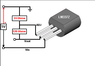
I want to regulate a -15V track to a value of -1.5V. Unless I miss-understood the component description I thought I could use the LM337 with the variable resistor R2 set to 24Ohm. The set up I have is that recommended in the revised November 2007 datasheet in Figure 1. I am unable to obtain the desired output value and have tried a different combination of voltages and resistors. From what I observe on the scope it seems to act as a voltage follower ie. no matter what my input voltage is (within the range) my Vout is always 0.5V away. Any help on understanding or alternative suggestions would be highly appreciated as I'd also like to use the LM317 to generate several positive values from a +15V rail.

Regards,

Hind

  • Using 120 ohm and 24 ohm should set Vout to -1.5V.

    I suggest that you double check your LM337 pin out connections, It's not exactly the same as the positive regs.

  • Dear Donald,

    Thank you for your prompt reply. I have checked the configuration again and again and it matches the one on the schematic you provided. The voltage supply I am using limits the output current and as I increase that gradually (the datasheet says it can handle up to 1.5A) the supply voltage gradually increases and so does the output voltage. It still seems to act as a voltage follower and the output voltage is well beyond -1.5V. The C1 and C2 capacitors I am using are the ones available in the Lab and I am unsure of whether or not they are discrete, not sure how that affects the circuit honestly.

    Best Regards,

    Hind

  • What is the exact part #?

    With R1 and R2 as the only load on the output, the input current should be approximately 10mA.


  • Hello,

    It's the LM337LZ/NOPB. The input current exceeded 200mA and I've already burned 2 capacitors.

    Many thanks,

    Hind

  •  

    Three pins, no TAB, hard to do it wrong. I'm out of ideas.

  • Hello,

    Thanks for being patient with me. I've tried setting up the LM317 for a change and have it working perfectly, only then did I realize that the datasheet I had for the negative regulator is the simple LM337 whereas the part I have is the LM337LZ. The pin order changes which explains the false results I had earlier. However although I am pleased with the output of the positive regulator (stable and only drawing 1mA input current), the negative regulator circuit is drawing around 67mA to output the desired -1.5V and the component is heating up. Any ideas on why?

    Hind

  • The 'Z' package is not especially ~thermal friendly~. With Vin at -15V that puts 13.5V across the device, so load current needs to be kept low to keep power dissipation down.

    If the only load on the output is the the two resistors used to set the output voltage (120 ohms and 24 ohms), then 67mA of current is simply wrong.

    Here's why:

    Minimum output current is set by the resistor between Vout and ADJ pins (aka 'R1'). The voltage between these two pins (aka Vadj) is the only voltage that this device regulates.

    The regulated voltage between Vout and ADJ pins (Vadj = 1.25V) creates a controlled constant current  through R1:

           I(R1) = (1.25V / R1) = (1.25V / 120 ohms) = 10.4mA

    This same current (10.4mA) flows through R2, which creates an offset voltage bwteen the ADJ pin and GND:

          V(R2) = 10.4mA x 24 ohms = 0.25V

    So the Vout is the sum of Vadj (across R1) and the offset voltage across R2:

          Vout = Vadj + V(R2) = 1.25V + 0.25V = 1.50V 

    All with 10.4mA of output current ... no more ... no less.

    If the device is properly regulating Vadj across R1 (i.e. 1.25V across 120 ohms), then I don't know where the extra 57mA of current is going to.


  • Yes I was measuring Vadj as 0.6V yesterday. Reconnected the whole thing and now record a perfect 10mA thank you very much!