This thread has been locked.

If you have a related question, please click the "Ask a related question" button in the top right corner. The newly created question will be automatically linked to this question.

MC33063: unstable output signals / overheating

Other Parts Discussed in Thread: MC33063A

Hello all

We have been using the MC33063 as a buck converter for many years. 21-30V input to 5V / 0.5A output
But now we are facing a problem with overheating.
Compared to the successful earlier application, we increased the output current by 20..30mA.
The MC33063A works in discontinuous mode.
Cin=820 uF,  Rsense=0.22 Ohm, Ct=470 pF, L=220 uH, Cout=330uF and 100nF

After a cold startup, the MC33063 works fine, but with increasing time or external heating,
the output signals get "distorted", and the MC33063 heats up until it would burn out.
The failed parts (10 pce so far) show the marking OAM, AX9C, G4.

By the way: the MC33063 from ON-Semiconductor does the job without any failure, even when heating it up with an external heater.

Any ideas what we are doing wrong ?

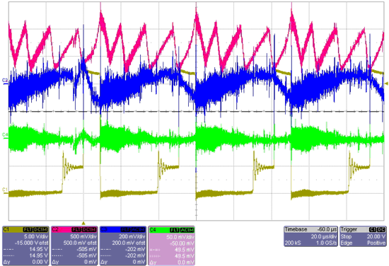
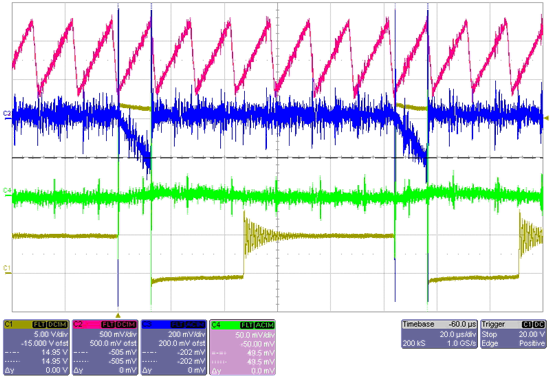
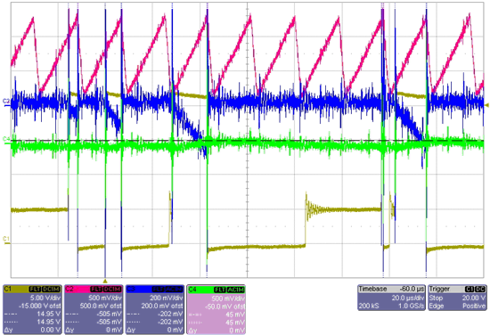
Measured signales on the scope:

channel 1, yello, switch voltage on IC pin 2
channel 2, red, timing voltage on IC pin 3
channel 3, blue, sense voltage on IC pins 1+7+8, AC-coupled
channel 4, green, +5V output, AC coupled

the problems I can see:

Red
the upper threshold of the timing signal is far to low.

Blue
sense-voltage should go to 24V instantly after switching OFF.
but here it goes up slowly with big noise.

Yello
the switching voltage does not go to -0.7V as usual, but it is around 0 V.

Yello
After that the inductor current is zero in the OFF phase,
the switch voltgae goes to 5V, but the ringing is much faster than usual.

A picture after a cold startup:

A picture with a MC33063 from ON-Semiconductor:

  • Adrian,

    The current limit is being reached then output transistor does not appear to turn all the way off. I have not seen this before.
    Does it happen just at the maximum load? Is is possible the the inductor is saturated?

    What is the part number for the coil and diode used?

    Regards,
    Ron Michallick


  • Hello Ron

    Yes, this happens either at maximum load or when I heat the circuit up just a little bit  with an external heater.
    We have been using this circuit for many years and have not been facing problems until recently.
    The device from ON-Semi is stable in exactely the same circuit, same load, even if heated up much.

    Coil: 220uH / 0.7A, Type CDR125-221MC form Sumida
    http://www.sumida.com/products/pdf/CDR125.pdf

    Diode:  1A / 200V, Type BYM12-200 from GI / Vsihay
    http://www.vishay.com/docs/88581/88581.pdf

    best regards,
    Adrian

  • Adrian,

    There is a lot wrong in the TI waveforms, but I can't determine what was the first thing to malfunction.
    I have three test ideas to figure out what is happening.

    1) The 0.22 resistor sets a current limit of 1.36A, Lower the current limit.
    2) Change the diode to a Schottky type.
    3) Connect pin 8 to a voltage 1V higher than VCC.

    Test one is because the coil rating is 0.7A, perhaps it gets close to saturation.
    Test two is because most app problems use a fast diode instead of a Schottky.
    Test three is to keep the pre-driver NPN from saturating.

    Regards,
    Ron Michallick


  • The issue is with the diode. You need *schottky* diode, otherwise internal parasitic diode starts to conduct in parallel to external one.

    As this diode is slow, you get lower efficiency and higher self-heating.