This thread has been locked.

If you have a related question, please click the "Ask a related question" button in the top right corner. The newly created question will be automatically linked to this question.

Deviation vs Rx filter bandwidth relationship, CC1110

 Hi

i use CC1110 SoC and i wonder which values should i set deviation to for different baud rates. In Smart RF Studio, some values are given. For example for 38.4Kbps deviation is 20KHz and RX filter bandwidth is 100KHz. What about for 20Kbps or for 10Kbps? How should i calculate these?


Thanks

  • A lot has to do with the crystal accuracy. 

    http://www.ti.com/general/docs/lit/getliterature.tsp?baseLiteratureNumber=swra122c

    Design note 005 has a lot of good information on this.

    Chris

  • Saci, 

    I agree with what Chris is saying and that at narrow bandwidths, the XTAL accuracy becomes very important factor in the entire system. But lets set that aside for a second and just discuss your original question. How do you estimate the occupied bandwidth of an FSK modulated signal.


    The occupied bandwidth for 98% of the transmitted power is determined from Carson’s

    Rule:  BW = 2(β + 1) x Fm or for 2FSK systems like ours  BW = 2 Fdiv + 1/Rb

    So, for your examples become: 38.4k + 2x20k = 78.4kHz,  20k + 2x20k = 60kHz  and 10k + 2x20k = 50kHz.

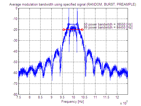
    Here is a Matlab simulation to show the same results, note in this case I had Matlab look for 99% bandwidth.

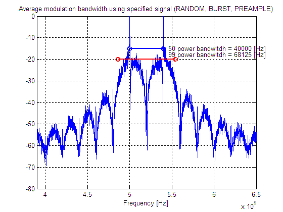
    And here is 20kbs and 20.6kHz frequency deviation

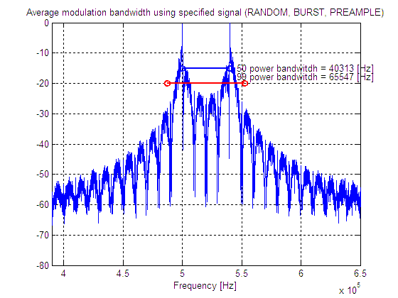
    and finally 10kbs and 20.6kHz frequency deviation

    I hope this helps.

    Regards,
    Thomas 


  • Thaks for your reply. these are very useful information. but i wonder that, what should be the deviation value for 10kbps or 20kbps for best communication range? i can use 5khz or 20khz or another deviation frequency for 10kbps. but whichone is best for data communication? what is the choosing criteria?


    Best regards.

  • Saci, 

    Please start with using the settings recommended by SmartRF Studio for the particular chip you are interested in, but in general the chips behave best if you keep the modulation index (Beta) from above between 0.25 and 2.

    Regards
    /TA 

  • I know this has been answered in another post, but I am adding my 2 cents anyway:

    Theoretically, there is an optimum separation/datarate setting if you simultaneously minimize the Rx filter bandwidth. Every halving of Rx filter bandwidth increases sensitivity with 3 dB whereas sensitivity vs separation/datarate (modulation index) decreases with about 1.5-2.5 dB per halving down to a certain limit where the loss increases very fast (I wouldn't go below a modulation index less than 0.5). Our experience is to that a modulation index of 1 is a good compromise. Note that the frequency offset between Rx and Tx needs to be taken into account when selecting the Rx filter bandwidth. 

  • Hi,

    I am trying to use other data rates on CC1110 and GFSK modulation besides the default ones specified in SmartRFStudio.

    In order to set the frequency deviation (to make modulation index = 1) and optimum RX filter BW (to have good sensitivity) I need to know the baseband BW of my GFSK signal (which I know depends on datarate). Can somebody give me a formula (I know it will be Carlson's) in order to directly calculate my required BW ?

    After I know that BW, is it right to set:

    1) Deviation = Maximum frequency of baseband signal

    2) Rx receiver's BW = BW of baseband signal + 4*ppm xtal*Frequency of operation (868MHz)

    Many thanks for your help,

    Jorge.


  • Required bandwidth can be approximated as BW of baseband signal + 4*ppm xtal*Frequency of operation , where BW of baseband signal = Data rate + 2 x frequency deviation.

    Example: 38.4 kbps data rate and +/-19.2 kHz deviation gives BW of baseband signal of 38.4 + 2 x 19.2 = 76.8 kHz

  • Hi Sverre,


    Many thanks for your answer. Horever I am a bit confused.

    Baseband BW is bandwidth before modulation (so I guess frequency deviation has nothing to do with BB BW), so I do not understand your statement :

    BW of baseband signal = Data rate + 2 x frequency deviation.

    I guess that you meant:

    1) BW of baseband signal = Data rate

    2) BW of modulated signal = Data rate + 2 * frequency deviation

    3) Required Rx filter BW= BW of modulated signal + 4*ppm xtal*Frequency of operation

    Thus, by setting a data rate, it gives me the correct frequency deviation in order to choose a desired modulation index (for instance B=1). Since B=(freqDeviation)/(BB BW) a B=1 gives FreqDev=Data rate

    Then by applying 3) I get the required Rx filter BW.

    Am I right?

    Many thanks for your help.

    Regards,

    Jorge.

  • Sorry, but I was a bit quick in previous reply (wrong wording). Correct shall be:

    Required RX filter bandwidth can be approximated as :Signal BW  + 4*ppm xtal*Frequency of operation , where Signal BW of = Data rate + 2 x frequency deviation.

    Example: 38.4 kbps data rate and +/-19.2 kHz deviation gives Signal BW of38.4 + 2 x 19.2 = 76.8 kHz

    For modulation index m= 1, the frequency separation, which is  2 x frequency deviation, is equal to the data rate.  I.e m = 2 x frequency deviation / data rate