This thread has been locked.

If you have a related question, please click the "Ask a related question" button in the top right corner. The newly created question will be automatically linked to this question.

Meandered Inverted F Antenna Impedance question using CC2530 on a custom PCB

Other Parts Discussed in Thread: CC2511

I am making a PCB for my system and I am using the TI Small SIze 2.4 GHz PCB antenna reference guide. I am using the matched balun-filter that is specifically designed for the CC253X, P/N 2450BM15A0002. The CC2511 reference guide (link above) shows two resistors close to the feed point.

What should the initial value of these two resistors be (R9, R10)?

Is there any more documentation to help me better understand this design and calculate these values?
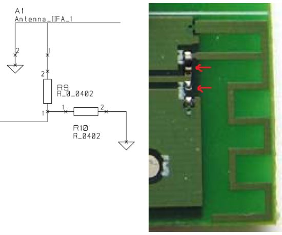
 

(Screenshot from the reference design of the CC2511.)


Thanks for any help.

  • The value for R9 R_0_0402 as suggested in the schematic itself should be 0 ohms.

    While R_0402 is usually a place holder or a do not mount. This is done, so that in the case of mismatch at the feed point of the antenna. The impedance can be better matched using a shunt element. Therefore, for the time being R10 should not mounted.

  • Thank you. I was confused by the labeling since it was 0 ohms while there was some type of resistor on those pads.

  • we usually advise people making the pcb's to almost always keep unmounted shunt components so they can improve on any mismatch. There are many factors which may cause mismatch and hence it's always prudent to have such elements in the prototype phase. Once you've characterized your boards then you can get rid of them if you do not use a shunt tuning element.

    Also, we encourage our customers to follow the reference design as closely as it is possible for them. The refrence design has been optimized and would give good results if followed closely.