Part Number: SW-DK-TM4C129X
Other Parts Discussed in Thread: EK-TM4C1294XL, EK-TM4C123GXL
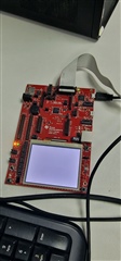
Using the TI board above to initialise a second board. I have gone through and programmed multiple of the second board using a JTAG link but on the 5th board I'm being shown this error message after unplugging the JTAG from the TI board. With a spare second TI board, attempted to retry but still getting the same error. I have tried unlocking the TI boards and updating the ICDI Firmware and still nothing. Sometimes after unlocking the board, I'll be shown the error "1" instead but will quickly go back to the "0" error. All of this is on the flash programmer build 1613.
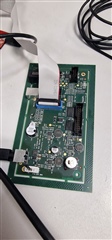
Also worth adding, the connectors are all correct and LEDs for power, 3.5V and 5V are illuminated as well as LCD screen. Using the Smart Programmer 2 software just as a test, the TI board is picked up and read leading me to believe its either the connector or cable.
Additional context, I am very new to using TI for board programming as the previous person in my workplace in charge of this left recently. I'm not entirely sure what it could be but I feel it may just be very simple since it only became an issue after unplugging the JTAG cable.