This thread has been locked.

If you have a related question, please click the "Ask a related question" button in the top right corner. The newly created question will be automatically linked to this question.

PROCESSOR-SDK-J784S4: How to configure BCM54810 Broadcom PHY in the device tree

Part Number: PROCESSOR-SDK-J784S4
Other Parts Discussed in Thread: TDA4VH, TEST2

Tool/software:

I am working on TDA4VH board with the SOC J784S4. I need to make the broadcom phy up. So I need to add to the device tree. Could you please tell me what I need to configure? And Is there any driver present already for this broadcom phy?

Your reply will help me a lot to proceed further.

Thanks in advance.

  • Hi,

    The phy driver for linux are present at "[PSDK-Linux-Insall-dir]/board-support/ti-linux-kernel-[commit-hash]/drivers/net/phy". There are driver for broadcom phy available, but you need to check if one is available for your specific phy part. If you are not able to find it, you need to ask broadcom for the same info.

    By default, you only need to specify the "reg" property (Phy ID on MDIO bus) for a phy to work. But phy vendors can require some additional properties. For these, you will have to ask broadcom.

    Addition references for Documentaion:

    • [PSDK-Linux-Insall-dir]/board-support/ti-linux-kernel-[commit-hash]/Documentation/devicetree/bindings/net/ethernet-phy.yaml
    • [PSDK-Linux-Insall-dir]/board-support/ti-linux-kernel-[commit-hash]/Documentation/devicetree/bindings/net/brcm,bcm4908-enet.yaml
    • [PSDK-Linux-Insall-dir]/board-support/ti-linux-kernel-[commit-hash]/Documentation/devicetree/bindings/net/broadcom-bcm87xx.txt

    Regards,
    Tanmay

  • Thanks for the reply, will check it out.

  • Hi, 
    I have added a device tree node for the broadcom phy (BCM54810) like the below,
    &main_cpsw1_mdio {
    status = "okay";
    pinctrl-names = "default";
    pinctrl-0 = <&main_cpsw2g_mdio_pins_default>;
    main_phy0: ethernet-phy@0 {
    reg = <0>;
    compatible = "broadcom,bcm54810", "ethernet-phy-ieee802.3-c22";
    };
    };
    Even though I added, I was not able to see th interface eth1 for my broadcom. 
    And also I am having one doubt, while building locally the broadcom.o file is not generating. Only for this we are not able to see the .o file. But for other phys example ADIN1300 (adin.o) are generated.

    Could you please assist me on this?
    I am pasting the log also here,
    [   2.516393] davinci_mdio 46000f00.mdio: davinci mdio revision 9.7, bus freq 1000000
    [   2.525656] davinci_mdio 46000f00.mdio: phy[0]: device 46000f00.mdio:00, driver ADIN1300
    [   2.533750] am65-cpsw-nuss 46000000.ethernet: initializing am65 cpsw nuss version 0x6BA02102, cpsw version 0x6BA82102 Ports: 2 quirks:00000000
    [   2.546598] am65-cpsw-nuss 46000000.ethernet: initialized cpsw ale version 1.4
    [   2.553804] am65-cpsw-nuss 46000000.ethernet: ALE Table size 64
    [   2.559950] pps pps0: new PPS source ptp0
    [   2.564087] am65-cpsw-nuss 46000000.ethernet: CPTS ver 0x4e8a010b, freq:500000000, add_val:1 pps:1
    [   2.612389] davinci_mdio c200f00.mdio: davinci mdio revision 9.7, bus freq 1000000
    [   2.620023] am65-cpsw-nuss c200000.ethernet: initializing am65 cpsw nuss version 0x6BA02102, cpsw version 0x6BA82102 Ports: 2 quirks:00000000
    [   2.632762] am65-cpsw-nuss c200000.ethernet: Use random MAC address
    [   2.639017] am65-cpsw-nuss c200000.ethernet: initialized cpsw ale version 1.4
    [   2.646136] am65-cpsw-nuss c200000.ethernet: ALE Table size 64
    [   2.652230] am65-cpsw-nuss c200000.ethernet: CPTS ver 0x4e8a010b, freq:250000000, add_val:3 pps:0
    [   2.662351] am65-cpts 310d0000.cpts: CPTS ver 0x4e8a010c, freq:250000000, add_val:3 pps:0

  • Hi,

    Can you cross check if the config for broadcom is enabled. This would be "CONFIG_BROADCOM_PHY".

    I think it is disabled by default in the SDK. You should change it to "y".

    Regards,
    Tanmay

  • Hi,
    Yes, by default it was not present and enabled. So I have already given CONFIG_BROADCOM_PHY=y in the device tree. Still the above mentioned issues I am facing. 

  • Hi Swedha,

    Can you provide your complete device-tree.

    How is the phy reset handled? Is it supposed to go through a GPIO? or is it driven by the SoC reset logic itself?

    If its driven by a GPIO, you will have to use a GPIO hog or "reset-gpios" property in device-tree. See "arch/arm64/boot/dts/ti/k3-j721e-evm-quad-port-eth-exp.dtso" for a reference of both hog and rest-gpios on our other EVM.

    Can you check if the phy is out of reset on the board.

    Regards,
    Tanmay

  • Thanks for the reply.
    device tree portion

    &main_gpio0 {
    status = "okay";
    };

    &mcu_cpsw {
    status = "okay";
    pinctrl-names = "default";
    pinctrl-0 = <&mcu_cpsw_pins_default>;

    cpts@3d000 {
    /* Map HW4_TS_PUSH to GENF1 */
    ti,pps = <3 1>;
    };
    };

    &davinci_mdio {
    pinctrl-names = "default";
    pinctrl-0 = <&mcu_mdio_pins_default>;

    mcu_phy0: ethernet-phy@0 {
    reg = <0>;
    ti,rx-internal-delay = <DP83867_RGMIIDCTL_2_00_NS>;
    ti,fifo-depth = <DP83867_PHYCR_FIFO_DEPTH_4_B_NIB>;
    ti,min-output-impedance;
    };
    };

    &mcu_cpsw_port1 {
    status = "okay";
    phy-mode = "rgmii-rxid";
    phy-handle = <&mcu_phy0>;
    };

    &main_cpsw1 {
    status = "okay";
    pinctrl-names = "default";
    pinctrl-0 = <&main_cpsw2g_pins_default>;
    };

    &main_cpsw1_mdio {
    status = "okay";
    pinctrl-names = "default";
    pinctrl-0 = <&main_cpsw2g_mdio_pins_default>;
    main_phy0: ethernet-phy@0 {
    reg = <0>;
    compatible = "broadcom,bcm54810", "ethernet-phy-ieee802.3-c22";
    };
    };

    &main_cpsw1_port1 {
    status = "okay";
    phy-mode = "rgmii-rxid";
    phy-handle = <&main_phy0>;
    };

    The below is the "arch/arm64/boot/dts/ti/k3-j784s4-evm-quad-port-eth-exp.dtso"

    // SPDX-License-Identifier: GPL-2.0
    /**
    * DT Overlay for CPSW9G in QSGMII mode using J7 Quad Port ETH EXP Add-On Ethernet Card with
    * J721E board.
    *
    * Copyright (C) 2023 Texas Instruments Incorporated - https://www.ti.com/
    */

    /dts-v1/;
    /plugin/;

    #include <dt-bindings/gpio/gpio.h>
    #include <dt-bindings/mux/ti-serdes.h>
    #include <dt-bindings/phy/phy.h>
    #include <dt-bindings/phy/phy-cadence.h>

    #include "k3-pinctrl.h"

    &{/} {
    aliases {
    ethernet1 = "/bus@100000/ethernet@c000000/ethernet-ports/port@1";
    ethernet2 = "/bus@100000/ethernet@c000000/ethernet-ports/port@2";
    ethernet3 = "/bus@100000/ethernet@c000000/ethernet-ports/port@3";
    ethernet4 = "/bus@100000/ethernet@c000000/ethernet-ports/port@4";
    };
    };

    &cpsw0 {
    status = "okay";
    };

    &cpsw0_port1 {
    status = "okay";
    phy-handle = <&cpsw9g_phy0>;
    phy-mode = "qsgmii";
    mac-address = [00 00 00 00 00 00];
    phys = <&cpsw0_phy_gmii_sel 1>;
    };

    &cpsw0_port2 {
    status = "okay";
    phy-handle = <&cpsw9g_phy1>;
    phy-mode = "qsgmii";
    mac-address = [00 00 00 00 00 00];
    phys = <&cpsw0_phy_gmii_sel 2>;
    };

    &cpsw0_port3 {
    status = "okay";
    phy-handle = <&cpsw9g_phy2>;
    phy-mode = "qsgmii";
    mac-address = [00 00 00 00 00 00];
    phys = <&cpsw0_phy_gmii_sel 3>;
    };

    &cpsw0_port4 {
    status = "okay";
    phy-handle = <&cpsw9g_phy3>;
    phy-mode = "qsgmii";
    mac-address = [00 00 00 00 00 00];
    phys = <&cpsw0_phy_gmii_sel 4>;
    };

    &cpsw9g_mdio {
    status = "okay";
    pinctrl-names = "default";
    pinctrl-0 = <&mdio0_pins_default>;
    reset-gpios = <&exp2 17 GPIO_ACTIVE_LOW>;
    reset-post-delay-us = <120000>;
    #address-cells = <1>;
    #size-cells = <0>;

    cpsw9g_phy0: ethernet-phy@17 {
    reg = <17>;
    };
    cpsw9g_phy1: ethernet-phy@16 {
    reg = <16>;
    };
    cpsw9g_phy2: ethernet-phy@18 {
    reg = <18>;
    };
    cpsw9g_phy3: ethernet-phy@19 {
    reg = <19>;
    };
    };

    &exp2 {
    qsgmii-line-hog {
    gpio-hog;
    gpios = <16 GPIO_ACTIVE_HIGH>;
    output-low;
    line-name = "qsgmii-pwrdn-line";
    };
    };

    &main_pmx0 {
    mdio0_pins_default: mdio0-pins-default {
    pinctrl-single,pins = <
    J721E_IOPAD(0x1bc, PIN_OUTPUT, 0) /* (V24) MDIO0_MDC */
    J721E_IOPAD(0x1b8, PIN_INPUT, 0) /* (V26) MDIO0_MDIO */
    >;
    };
    };

    &serdes_ln_ctrl {
    idle-states = <J721E_SERDES0_LANE0_PCIE0_LANE0>, <J721E_SERDES0_LANE1_QSGMII_LANE2>,
    <J721E_SERDES1_LANE0_PCIE1_LANE0>, <J721E_SERDES1_LANE1_PCIE1_LANE1>,
    <J721E_SERDES2_LANE0_PCIE2_LANE0>, <J721E_SERDES2_LANE1_PCIE2_LANE1>,
    <J721E_SERDES3_LANE0_USB3_0_SWAP>, <J721E_SERDES3_LANE1_USB3_0>,
    <J721E_SERDES4_LANE0_EDP_LANE0>, <J721E_SERDES4_LANE1_EDP_LANE1>,
    <J721E_SERDES4_LANE2_EDP_LANE2>, <J721E_SERDES4_LANE3_EDP_LANE3>;
    };

    &serdes_wiz0 {
    status = "okay";
    };

    &serdes0 {
    status = "okay";

    assigned-clocks = <&serdes0 CDNS_SIERRA_PLL_CMNLC>, <&serdes0 CDNS_SIERRA_PLL_CMNLC1>;
    assigned-clock-parents = <&wiz0_pll1_refclk>, <&wiz0_pll1_refclk>;
    #address-cells = <1>;
    #size-cells = <0>;

    serdes0_qsgmii_link: phy@1 {
    reg = <1>;
    cdns,num-lanes = <1>;
    #phy-cells = <0>;
    cdns,phy-type = <PHY_TYPE_QSGMII>;
    resets = <&serdes_wiz0 2>;
    };
    };


  • Hi Swedha,

    Please provide the other details when you can as well.

    Regaards,
    Tanmay

  • Hi, 
    I was not able to figure out how the phy got reset. I have checked the schematic also. But not able to figure out which pin. But I went through the datasheet of BCM54810. It was mentioned like the below,
    The PHY address for the BCM54810 is determined by the state of the PHYA[0] and TEST3/TEST2 pins. I have tried search the pins in the schematic. But it was not present. Is there any relation between this and the device tree node(reg = <0>) we wrote. 
    And also one doubt, Is there will be the issue due to object file not generated for the broadcom.c file?
    Could you please tell how can I proceed further? 
    Because everything was as same we did like the other phy (ADIN1300)

    Thanks in advance.

  • Hi,

    And also one doubt, Is there will be the issue due to object file not generated for the broadcom.c file?

    Once you enabled the config, the broadcom.o should be generated right. Also can you confirm that it is "y" and not "m" in the ".config" file generated.

    At runtime, you can run "zcat /proc/config.gz | grep BROADCOM" to see if "CONFIG_BROADCOM_PHY=y" is present.

    s there any relation between this and the device tree node(reg = <0>) we wrote. 

    The phy address is the reg property in the device-tree node. It is needed to probe the phy.

    Could you please tell how can I proceed further? 

    Can you get this information from any hardware team.

    In the meanwhile, you can try to probe the phy reset line using oscilloscope to see if any reset is captured on the line. If not, the phy is not getting a reset signal and this has to be investigated further. If the reset is coming from GPIO, we can update this with device-tree (we need to know which GPIO for this). If the reset is coming from PMIC, then hardware will need to be investigated.

    Regards,
    Tanmay

  • Hi,
    First of all thanks for the immediate response.

    At runtime, you can run "zcat /proc/config.gz | grep BROADCOM" to see if "CONFIG_BROADCOM_PHY=y" is present.

    As you suggested I have checked this in my hardware after flashed the image to the board. It was showing like the below. It was not set. But later we enabled the bcm54xxx in the menuconfig GUI. Then the .o got generated and it is saving to .config  and built and flashed that image only. But still the same behaviour. It is because it was saved in .config and not able to use this .config. Because it is taking the defconfig.
    Could you please tell what's your thought on this?

    The phy address is the reg property in the device-tree node. It is needed to probe the phy.

    But we are just assmuning and giving as 0. Because, while seeing/surfing net we are not able to find any reference on how to give this reg value. Even in the .yaml files of several broadcom, it was not clear to give. Could you please suggest on how to give this reg value?

    Can you get this information from any hardware team.

    Sure.

    Awaiting for your reply


    Thanks&regards,
    Swedha R

  • Hi Swedha,

    Because it is taking the defconfig.
    Could you please tell what's your thought on this?

    Can you share details on your build flow. 

    Clearly the config "CONFIG_BROADCOM_PHY" is not being added to the kernel.

    Could you please suggest on how to give this reg value?

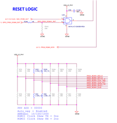
    This will also come from your schematic. As a reference, I am attaching screenshot from our EVM schematic.

    The PHY_ADD you can see is the PHY_ID. It depends on the resistor divide circuits and the value of resistors used.

    Regards,
    Tanmay

  • Hi,

    Clearly the config "CONFIG_BROADCOM_PHY" is not being added to the kernel.

    We resolved the issue in generating the broadcom.o by removing the line CONFIG_BROADCOM_PHY=n from another file (/home/user/ti-processor-sdk-linux-adas-j784s4-evm-09_02_00_05/board-support/ti-linux-kernel-6.1.80+gitAUTOINC+2e423244f8-ti/kernel/configs/ti_arm64_prune.config).
    We are able to see the ouput as set for the command you have shared  ("zcat /proc/config.gz | grep BROADCOM" ). But still in the log we are not able to see the driver is loaded. I don't what else is needed to add in the device tree apart from the below to just probe the driver.
    main_phy0: ethernet-phy@0 {
    reg = <0>;
    compatible = "broadcom,bcm54810", "ethernet-phy-ieee802.3-c28";
    };

    The compatible is correct right? that itself is enough to probe the driver right?

    This will also come from your schematic. As a reference, I am attaching screenshot from our EVM schematic.


    I have checked in my schematic. But there is no direct mention about it. Because it was a custom board. But I have tried to change the register value based on some 5 bits register mentioned in the datasheet.

    We have tried all the possible methods even putting printk statements in the code. Nothing is working out for us.

    Thanks&regards,
    Swedha R

  • Hi Tanmay,
    Could you please get back asap on the above reply?

    Thanks in advance,
    Swedha R

  • Hi,


    The compatible is correct right? that itself is enough to probe the driver right?

    No. The phy probe sequence goes something like following:

    • An ethernet phy is always defined inside a MDIO module. It is davinci-mdio in our case. MDIO is something we use to communicate with the phy. But this communication over MDIO requires a PHY_ADDR. Thiscomes from the reg property.
    • Based on the PHY_ADDR, we start communicating with the phy and get a PHY ID from its registers. This ID is unique to the phy part number. The same PHY ID is also used to in phy drivers.
    • Once linux get the PHY ID, it finds the corresponding driver based on this PHY ID and then runs its probe.
    • The compatible string in a phy's case is not related to its driver but is rather used for specifying some corner cases. It is not mandatory, but the compatible strings used by you doesn't hurt as well. You can remove those.
    compatible = "broadcom,bcm54810", "ethernet-phy-ieee802.3-c28";

    I am assuming this is "ethernet-phy-ieee802.3-c22" and "c28" is a typo. But as I said earlier doesn't matter.

    I have checked in my schematic. But there is no direct mention about it. Because it was a custom board.

    Then you have to go to the designer to confirm this. This is crucial.

    One thing you can try is to just scan the bus for all addresses. If you do not see any response, then that probably means that the phy is not out of reset and you will have to get confirmation on how is the reset handled from the schematic designer.

    To scan the whole bus, you can use the following patch:

    diff --git a/drivers/net/ethernet/ti/davinci_mdio.c b/drivers/net/ethernet/ti/davinci_mdio.c
    index 8ed2f89eb..2c167c3c8 100644
    --- a/drivers/net/ethernet/ti/davinci_mdio.c
    +++ b/drivers/net/ethernet/ti/davinci_mdio.c
    @@ -685,9 +685,9 @@ static int davinci_mdio_probe(struct platform_device *pdev)
            if (dev->of_node && of_get_child_count(dev->of_node))
                    data->skip_scan = true;
     
    -       ret = of_mdiobus_register(data->bus, dev->of_node);
    -       if (ret)
    -               goto bail_out;
    +       // ret = of_mdiobus_register(data->bus, dev->of_node);
    +       // if (ret)
    +       //      goto bail_out;
     
            /* scan and dump the bus */
            for (addr = 0; addr < PHY_MAX_ADDR; addr++) {

    By the way, was the schematic for the custom board reviewed by TI?

    Regards,
    Tanmay


  • Thanks for the response Tanmay.
    I have commented the data->skip_scan = true; in the davinci_mdio.c.
    But in the log already probed driver (ADIN1300) itself is not coming now. I am attaching both the logs below.

    And regarding the reg we need to give, I found in the datasheet there will be 4 possible phy addresses they mentioned. But even after tried that one also it's not probing correctly.

    And I am not sure whether ti reviewed the board or not?


    Old Log:
    [   2.516393] davinci_mdio 46000f00.mdio: davinci mdio revision 9.7, bus freq 1000000
    [   2.525656] davinci_mdio 46000f00.mdio: phy[0]: device 46000f00.mdio:00, driver ADIN1300
    [   2.533750] am65-cpsw-nuss 46000000.ethernet: initializing am65 cpsw nuss version 0x6BA02102, cpsw version 0x6BA82102 Ports: 2 quirks:00000000
    [   2.546598] am65-cpsw-nuss 46000000.ethernet: initialized cpsw ale version 1.4
    [   2.553804] am65-cpsw-nuss 46000000.ethernet: ALE Table size 64
    [   2.559950] pps pps0: new PPS source ptp0
    [   2.564087] am65-cpsw-nuss 46000000.ethernet: CPTS ver 0x4e8a010b, freq:500000000, add_val:1 pps:1
    [   2.612389] davinci_mdio c200f00.mdio: davinci mdio revision 9.7, bus freq 1000000
    [   2.620023] am65-cpsw-nuss c200000.ethernet: initializing am65 cpsw nuss version 0x6BA02102, cpsw version 0x6BA82102 Ports: 2 quirks:00000000
    [   2.632762] am65-cpsw-nuss c200000.ethernet: Use random MAC address
    [   2.639017] am65-cpsw-nuss c200000.ethernet: initialized cpsw ale version 1.4
    [   2.646136] am65-cpsw-nuss c200000.ethernet: ALE Table size 64
    [   2.652230] am65-cpsw-nuss c200000.ethernet: CPTS ver 0x4e8a010b, freq:250000000, add_val:3 pps:0
    [   2.662351] am65-cpts 310d0000.cpts: CPTS ver 0x4e8a010c, freq:250000000, add_val:3 pps:0


    Awaiting your reply,
    Thanks in advance
    Swedha R

  • Hi,

    It seems like the phy is not coming out of reset as there are no live phy's after scanning all 32 addresses. So you will have to find out how phy reset is handled.

    Regards,
    Tanmay

  • Hi, 
    Thanks for the reply.
    But how then before the ADIN1300 phy is detected?

    Thanks and regards,
    Swedha R

  • Hi Swedha,

    The ADIN1300 phy can be cotrolled by different reset sequences. SO it can be controlled directly from the SoC reset signal while the broadcom phy will be controlled by GPIO.

    Regards,
    Tanmay

  • Hi Tanmay, 
    Thanks for the response.

    Yeah as you told we have confirmed that the ADIN1300 phy was controlled directly from the SOC. But for our broadcom phy we need to do warm reset. We found the below thread mentioned on how to do it for RTOS(by calling API Sciclient_pmDeviceReset(uint32_t timeout) ). But for us how we need to do it in linux A72 core? Could you please assist on this? 
    Thread: https://e2e.ti.com/support/processors-group/processors/f/processors-forum/1116692/tda4vm-q1-tda4vm-q1-how-toreset-sbl


    Awaiting your reply,
    Thanks & regards,
    Swedha R

  • Hi Swedha,

    by calling API Sciclient_pmDeviceReset(uint32_t timeout)

    This will reset your SoC. This is most probably not what you want. This will restart A72 and all the cores. You only want to reset the phy. For this, you only need to toggle the pin which goes to the phy reset. It is unlikely that this pin will come from SoC warm reset only and not come from SoC hard reset. Hard reset is almost always subset of soft reset. Have you confirmed this for sure?

    Can you just share the schematic here.

    Regards,
    Tanmay

  • Hi Tanmay,
    Thanks for the immediate response.
    For some reason I can't able to share the schematic here. But the pin that is going to phy reset is resetstatz.  I am attaching the snaps of the pin details from the TDA4VH datasheet.

    With this pin how we need to do the phy reset?


    Thanks & regards,
    Swedha R

  • Hi Swedha,

    I have to look into this. Let me get back to you on this by next Wednesday.

    Regards,
    Tanmay

  • Hi Tanmay,
    Sure. Will await for your reply. 

    Thanks and regards
    Swedha R