Tool/software:
Hello all,
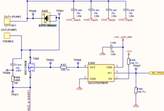
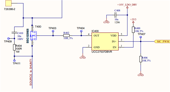
In our projects, we plan to use UCC27537DBVR driver IC for the Mosfet BSC123N08. We used 5020YM IC driver before and now we would like to replace your products.
For a better understanding, I will attach the part of schematics which can give you an overview:
But we faced lots of difficulties in the input PWM comes from the MCU and out signal for Gate mosfet.
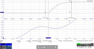
Input PWM from MCU:
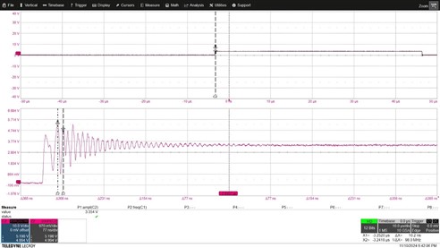
Out from DRV to Gate:
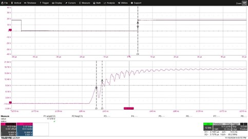
While everything is very fine with the MI5020YM, we have lots of issue with the UCC27537DBVR and it leads to EMC failure.
Can you please let me know if for the UCC27537DBVR should I add any other parts on the schematics?
Best regards,