This thread has been locked.

If you have a related question, please click the "Ask a related question" button in the top right corner. The newly created question will be automatically linked to this question.

TPS4811-Q1: TPS4811-Q1 over current protection

Part Number: TPS4811-Q1

Hi team  

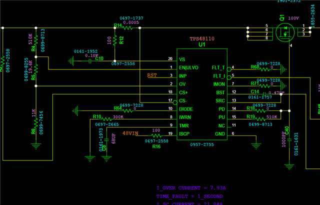
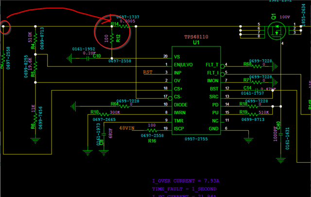
We are using the TPS48110 in our new board.

We used the design calculator from calculate the Riwrn Rsns Riscp values.

We chossed value of 3mohm for Rsns 

We choosed value of 50 Kilo ohm for Riwrn to set the over current protection threshold at ~8A

We chossed vlaue of 4.7 Kilo ohm for Riscp to set the short circuit protection threshold at ~26

But actually the current is cutted off ( over current protection ) at ~6.8A


please advise which values of Riwrn, Riscp should i use for setting the over current at 8A and the short circuit protection at 26A 

thanks 

  • Hi Meori, 

    Your math looks good. Looks like you are seeing some accuracy issues. Can you confirm the accuracy of your resistors is about 1%?

    To set the IWRN value higher you should reduce your RIWRN value. 

    Thanks,

    Sarah

  • Hi Sarah 

    Does such amount of variance in resistor value can cause to such variance in over current threshold 

    We are talking about 6.8A Vs 8A ?

  • Hi Meori, 

    Not for 1%. I already did the math and calculated worse expected OCP would be ~7.5A vs 8A not 6.8A. I have a meeting later this week to discuss this topic internally and can add clarification by end of week. 

    In the meantime I was just asking to verify the resistors were chosen with tight tolerance. 

    Thanks, 

    Sarah

  • Hi Sarah

    yes, the resistor are with 1% tolerance 

  • Ok. No problem. Ill update you tomorrow based on my meeting. 

    Thanks, 

    Sarah

  • Hi Sarah 

    in the mid time i attached the scheme here 

    please review it 

    thanks 

  • Hi Meori, 

    1. Add protection resistor to INP (4.7kohm)
    2. Consider adding placeholder for RTMR in parallel to CTMR
    3. If you have EMI concerns place ferrite beads in series with CS+/-

    Thanks, 

    Sarah

  • Hi Sarah 

    1) thanks for your comments 

    2) i wail for your feedbacks regarding the incompatibility of RIWRN's formula and the results i saw..

    thanks  

  • Hi Meori, 

    I did speak with our Systems engineer about this today. 

    Can you check your IMON accuracy? You will need to populate a resistor here. A typical explanation for IWRN inaccuracy could be sense pin/ shunt resistor placement. If you are also seeing inaccuracy in IMON then this is the likely culprit. 

    Consider the importance of a Kelvin connection with the RSNS and the CS+/- pins. Ideally you will have CS+/- connected directly to the RSNS pads not along the VBAT trace.. I see from your schematic that you have CS+ routed to the far left of the shunt resistor, make sure this isnt how the layout is actually routed. 

    Secondly make sure the CS+/- lines are length matched. Its important to consider any loses due to extra length on one compared to another since we are dealing with mV of delta. 

    Thanks, 

    Sarah

  • Hi Sarah Thanks for your replay

    we will check it (kelvin connection) and implement it in the next layout if needed. 1) Do you recommend of using 4 wire shunt resistor ? 2)

    i noticed to that paragraph from the data sheet of TPS4811-Q1:

    Does it mean that if we want to get high accuracy of OC/S.C threshold we should use Rsns that give 30mv at the desired current : for example, for getting OC cut off at 8A we should Rsns= 30mv/8A =3.75mohm ? thanks

  • Hi Meori, 

    The existing sense pins provide the Kelvin connection you need. You need to make sure that your board traces are connected directly to the shunt pads. 

    The RSNS value should be chosen to keep the VSNS close to the 25-30mV range. This is described in the applications section below. 

    You can see from the E.C table below how the lower VSNS option noise can impact accuracy (6mV vs 30mV).

    For your components your VSNS = 40mV. I would not expect this to dramatically impact accuracy as you are not on the lower end, but you can experiment with a different RSNS and verify. 

    Thanks, 

    Sarah

  • Hi Sarah 

     You need to make sure that your board traces are connected directly to the shunt pads

    > Did you mean that CS- should be connected directly to the shunt. CS+ can't be directly connected because it should be connected to Rset

    please approve 

  • Hi Meori, 

    Yes CS+ should be connected through the RSET resistor. This trace should be connected directly to the RSNS pad. The point here is that we do not want you to place the trace for the CS+/- pins just anywhere along the VBATT line. This is theoretically the same thing,, but could impact accuracy if not connected directly at shunt pads. 

    Thanks, 

    Sarah

  • Hi Sarah 

    I did not understand where should i place the traces for CS+/CS-

    please mark it, on the scheme below :

    thanks 

  • Hi Meori, 

    Please reference the layout example section in our DS shown below. The key here is that the races from CS+/- are tied directly to RSNS pads (circled in red). You need to make sure that CS+ and RSET are not connected directly to Vin pour like shown with red X. 

    You can also reference the TPS48111 EVM. The intention with the schematic is that Vs and EN connection are made before the RSNS connections and the sense pins are connected at the RSNS nodes. 

    For your drawing I have shown the same fix, but this is just a schematic. The important thing is that your layout traces do what is shown in section 9.5.2.

    I hope this is helpful. 

    Thanks,

    Sarah

  • Hi Sarah 

    thanks for your information 

    we will take it in account in the next layout. 

    in the mean time, i have another question regarding the below data :

    does it mean that we must take the 30.6mv/Ioc to get the Rsns value ( and not the 25mv as you wrote above) ?

  • Hi Meori, 

    No. The above table is a representation to help you determine accuracy. This indicates that values much lower than the 25mV (8-12mV) results in worsened accuracy. This is what is meant by "values near the low threshold 10 mV can be affected by system noise.".

    Effectively the more voltage differential between the CS+/- pins the more accurate the IWRN can be. This means a larger RSNS resistor that creates a higher voltage drop.

    The downside to this is high power dissipation. This is what is meant by "To minimize both concerns, 25mV is selected". The 30mV in the EC table is a validated result to indicate tighter accuracy in this range without needing to oversize the RSNS. 

    Thanks, 

    Sarah

  • hi Sarah 

    Does it mean that Vsns_wrn ( OCP threshold ) depended in Riwrn values?

  • Hi Sarah 

    please explain how can i configure the Vsns_wrn?

    thanks 

  • Please use eq(13) as shown above. VSNS_WRN can be appropriately selected as 25mV. 

    Thanks, 

    Sarah

  • Hi Sarah 

    Our load is a capacitive load  ( motor) with 160uF 

    when the external FET ( IAUC40N08S5L140) is turn ON while it connected to this motor, there is inrush current of about 30A  (see below  each volt is 1A) 

    the Isc  threshold is configured to 25A thus the TPS 48110 regulator is turn off the FET and the FLT I is going low 

    there is resistor of 82k ohm is series to the gate ( as shown below )

    when i added capacitor of 1nf from gate to gnd there is no inrush current but when i perform full short circuit  ( out to gnd ) the FET is damaged

    what should i do ?

    please advise 

  • Hi Meori,

    The team is out on holiday until December 6 and will provide a reply then.

    Please let us know if this is an urgent request.

    Thanks,

    Patrick

  • Hi Patrick

    No, its not an urgent request

  • Hi Meori, 

    The capacitor from gate to ground is good and will slow down your FET turn on to dissipate the INRUSH current safely. We suggest a resistor in series with this to help dampen the discharge of that capacitor. 

    Are you performing the Short to GND test when the FET is fully enhanced? Or are you enabling into Short? 

    How are you physically applying the short? 

    What is the damage you are seeing on the FETs? 

    Thanks, 

    Sarah

  • Hi Sarah

    i am performing the short to GND when the FET is fully enhanced ( there is 48V at the output) 

    physically i apply the short by a switch 

    the FET is actually out of action ( i think its burned) 

    thanks 

  • Hi Meori, 

    A few thoughts. 

    1. Do you have any confirmation before the FET was damaged if the device recognized the event as SCP (based on CTMR vs FLT_I timing) and how long it took to respond? Just wanting to make sure that this wasn't an OCP event which you have your shut down time set to 1 second. 
      1. The device should consider 35A an SCP and shut off < 10us. The should be more than fast enough to protect your FET. 
    2. Additionally typically short to ground tests are performed with some resistance and small inductance on the line to mimic an actual wire. This is important as a short to GND without any line resistance would have infinite current increase. 
    3. Its good you are able to confirm FLT_I. This indicates device was able to recognize and respond to current event. When you power device back on with damaged FET does FLT_I remain on? Can you verify if there is a short from G-S or D-S on your burnt FET first?

    Thanks, 

    Sarah

  • Hi Sarah

    for get over this  inrush current from our motor ( capacitive load)  i use R1=100K and C1 = 100pf for control the slew rate of the FET turn ON ( as you recommend in the data sheet ( below) 

    but when the FEF turn ON under load of 8A ( when i perform reset after the FET was enhanced and conduct current ) i saw that it cant turn on 

    what value of CBST should i use and how it affect the rise time of the FET? 

  • Hi Meori, 

    Please take a look at our online calculator to help select these values.

    The DS recommended values are just a starting point. Actual FET INRUSH and charge can change these requirements. Start by calculating expected INRUSH based on output capacitance and needed turn on time. 

    From here you can back calculate the slew rate controls to accommodate this specific INRUSH (this is where calculator is very helpful). 

    The CBST will also change based on the slew rate controls you add. 

    https://www.ti.com/product/TPS4811-Q1#design-tools-simulation

    For future inquiries please file new E2E ticket to help prevent this one from getting any larger. It also helps others searching for similar inquires. 

    Thank you, 

    Sarah