This thread has been locked.

If you have a related question, please click the "Ask a related question" button in the top right corner. The newly created question will be automatically linked to this question.

SN65HVD1780-Q1: Design matching questions

Part Number: SN65HVD1780-Q1

Hi, team,

I have some questions about SN65HVD1780-Q1 match design as below. Please look into it and give your suggestion.

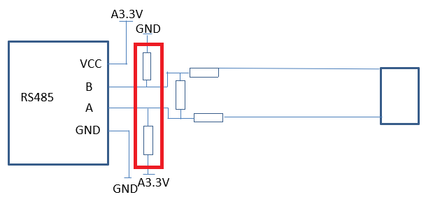
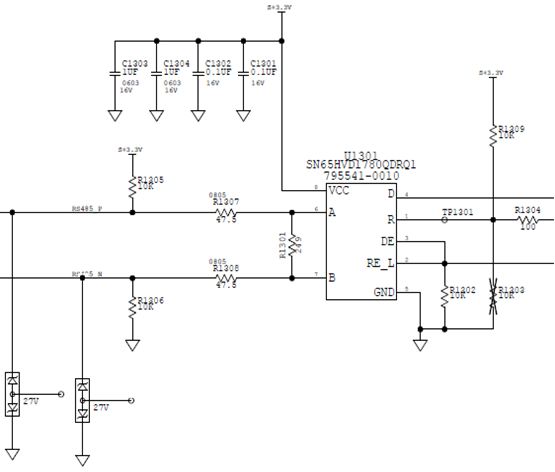
1. Below is slave side transceiver design. For master side transceiver, do we need to design isometric differential lines of B/A? What is the differential impedance?


2. Does terminating resistor need to be the same between master and slave side?

3. What is the requirement of damping resistor on differential line?

Thanks.

Johnny

  • Johnny,

    You might want to reference this app note to get a better understanding of RS-485:

    http://www.ti.com/lit/an/slla272c/slla272c.pdf

    The transmission lines used as typically differential in nature, meaning that they have equivalent lengths between both pairs and a controlled differential characteristic impedance.  This becomes important especially at higher data rates where the delay through the cable becomes significant with respect to the transition times of the signal waveforms.

    Most RS-485 applications use a 120-Ohm environment, meaning that the differential characteristic impedance of the transmission line is 120 Ohms and the termination resistance values match it.  A driver is typically specified to support enough output current to handle two terminations in parallel (as well as some additional leakage current into each receiver), so these two termination are typically placed at each endpoint of the bus.  Matching the end-of-line terminations to the cable impedance prevents reflections that might otherwise occur when a signal is incident upon a discontinuity in impedance.

    It is OK to use other resistances, though, if needed by the application.  And, in many cases termination is not critical because the signaling rate is low or the cabling distance is short.  For a given set-up, you can evaluate signal integrity by checking the differential lines and receiver output on an oscilloscope to make sure the data is being received properly.  When changing the termination resistances, though, I would recommend to keep the total equivalent resistance between the A and B lines above 54 Ohms (since this is the worst-case load condition that is assumed when specifying the driver circuits).

    Series damping resistors are optional and are typically used to provide some additional protection to the transceiver by limiting input currents.  These can cause attenuation when paired with bus termination, though, so you should be careful not to use values that are too high.

    Please let me know if you have any additional questions.

    Regards,
    Max

  • Max,

    Thanks for reply. I have another question.

    1. Below is customer's connection 1, with B pull down to GND and A pull up to VCC.

    2. There is another connection 2, with A pull down to GND and B pull up to VCC.

    What is the difference between these two connection? And what is the suggested application scenarios of these two connection?

    Thanks.

    Johnny

  • Hi Johnny,

    The pull-up/pull-down resistors are used to bias the inputs to the receiver to a known state (either high or low) during periods where the bus is not being strongly driven by an active transceiver or if the cable becomes disconnected.  So, the desired receiver output state in this case would determine which line should be pulled high and which line should be pulled low.

    Most UART communication lines will remain in the logic-high state while idle and signal the beginning of a word or frame with a logic-low "start" bit.  In this case it is best to tie A high and B low so that the differential line is held at a high level when undriven.  Then, once a transceiver becomes active at the start of a transmission it can begin by sending this start bit.

    Pulling B high and A low would have the opposite effect - it would make the "default" state of the bus low.  It is possible that the customer is using a data protocol that requires this, but it tends to be very uncommon.  So, you may want to double-check whether this connection were intended or whether it was just a mistake.  (Sometimes there is some confusion about which half of the A/B differential pair should be considered "non-inverting" and which should be considered "inverting.")

    By the way, this idle/open-state biasing is often referred to as "failsafe biasing," and you can read more about it in this blog:

    https://e2e.ti.com/blogs_/b/industrial_strength/archive/2016/12/06/rs-485-basics-two-ways-to-fail-safe-bias-your-network

    Regards,
    Max