

This post is co-authored by Bharath Vasan.
In part three of this five-part blog series, we introduced a simple control-loop model for distortion in an operational amplifier (op amp), repeated here in Figure 1. We also included a pop quiz that we’ll continue discussing in this post, so please read that installment first if you haven’t done so already. Everything we discuss here will make more sense that way.
The model in Figure 1 is useful in illustrating how a source of distortion would be attenuated by the loop gain of the system, but it does not reveal anything about the actual mechanism of distortion and why it would increase with low load impedances.
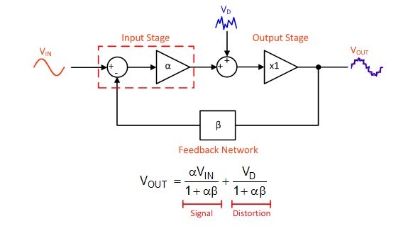
Figure 1: A control-loop diagram of an op amp that includes an internal source of distortion and the resulting transfer function
In an op amp’s output stage, the distortion does not come from a separate source injected into the loop; it arises from variations in the impedance of the output stage with the load voltage or current. As illustrated in Figure 2, the actual gain of the output stage (AOS) can be represented as a voltage divider consisting of the load impedance (RL) and the impedance of the output stage (ROUT).
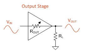
Figure 2: The output stage gain depends on output impedance and load impedance
Therefore, the gain of the output stage can never be exactly 1, and it also depends on the load impedance (Equation 1):
ROUT separates into two terms: a static impedance (RO) and a dynamic one that varies as a function of the output voltage and output current (ΔR[VO, IO]). See Equation 2:
It is this varying output impedance that produces distortion. For example, if ROUT decreases when the output stage is sourcing current, then the overall gain of the output stage would be greater for positive voltages compared to negative ones, and would distort the input signal.
Substituting the expression for ROUT back into Equation 1 offers some insight into the role that load impedance plays:

Notice that ΔRO is divided by the load impedance. Therefore, reducing the load impedance will cause greater variations in the gain of the output stage and produce more distortion (answer C from the pop quiz in part 3 of this series).
To show this effect, my colleague Bharath Vasan simulated the output stage gain versus the output voltage for the OPA1688, a general purpose audio op amp, and the OPA1622, an audio op amp designed for low impedance loads. He used 604-Ω and 32.4-Ω loads for these simulations.
Figures 3 and 4 show the results. In the 604-Ω load case, both amplifiers displayed stable gain over the range of output voltages simulated. But in the 32.4-Ω case, the differences between the two output stages became apparent. The gain deviation was worst near 0V, where the load current transitioned from one output transistor to another. This is commonly known as output crossover distortion. In the OPA1622, the output crossover region is greatly reduced, and the gain deviation in this region is minimized.

Figure 3: Output stage gain vs. output voltage for a 604-Ω load

Figure 4: Output stage gain vs. output voltage for a 32.4-Ω load
Congratulations to those of you who answered “D” to the pop quiz in part 3! High-frequency distortion depends on both the loop gain of the amplifier and the distortion of the output stage.
When developing the OPA1622, we took a dual approach to reduce distortion. Not only did we maximize the open-loop gain of the amplifier at audio frequencies, but we reduced the intrinsic distortion of the output stage by addressing the dynamic component of the output impedance.
The result of this improved output stage is instantly recognizable in the distortion measurements. The measurement performed in Part 3 on the OPA1688 is now repeated in Figure 5 with the OPA1622. Notice the improvement in high frequency distortion for all load impedances.
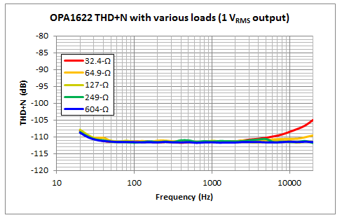
Figure 5: THD+N vs. frequency curve for an OPA1622 with various loads
In the final installment of this blog series, we’ll take a look at the shutdown feature of the OPA1622 and how we minimized audible “clicks” and “pops” when the amplifier is enabled and disabled.
Additional resources
- Watch a four-part TI Precision Labs – Op Amps training course on low-distortion design.
- Search TI Designs – Precision reference designs to help get your next design started.
- Read the OPA1622 and the OPA1688 datasheets.


