

This post was co-authored with John Caldwell.
In the final installment of this five-part blog series, I will discuss pop/click noise in operational amplifiers (op amps) driving headphone loads, and some techniques to minimize them. The previous posts discussed power considerations for headphone loads, impedance of headphones, and sources of headphone amplifier stability and distortion.
Undesirable audible noise resulting from applying power or changing operational modes in an audio system is commonly called a pop or a click. This effect is of extreme concern in high-fidelity headphone systems due to the high efficiency of the headphone drivers. Even relatively small transients in the signal voltages will produce loud and unpleasant sounds from the headphones. In order to improve the user experience and prevent damage to headphones or other sensitive electronics, many systems employ circuitry to suppress transient signals from the amplifier output during power-up.
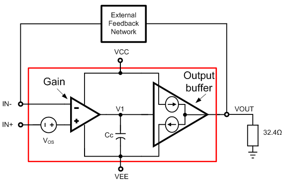
Figure 1: Op amp driving a headphone load
Let’s look at some of the common sources of pop/click noise in an op amp.
Figure 1 is a simplified block diagram of an op amp driving a headphone load. It consists of two stages – a gain stage and an output buffer – as well as a compensation capacitor, Cc, and an offset voltage, Vos. The output buffer is a unity gain stage capable of sinking and sourcing current as shown.
Pop/click noise is typically associated with transients at the output pin of the op amp. The chief sources of pop/click noise are:
- Power-supply ramp: During power-on, VCC and VEE gradually ramp up. Until the op amp reaches its minimum supply requirement, it has not yet attained steady-state operation and is not regulating the output. During this period, large transients could result at the output pin. A power-off where VCC and VEE ramp down could be accompanied by similar transients, as could asymmetric ramping of VCC and VEE.
- Enabling/disabling the amplifier: Many op amps include options to enable or shut down the device. The enable command turns on the op amp’s internal bias circuitry. As the bias currents come up, the gain stage starts charging the compensation capacitor to the appropriate voltage, the sourcing and sinking currents in the output buffer start stabilizing, and the op amp approaches steady state. During this phase, unequal sourcing and sinking currents in the output buffer result in current being injected into the load. This could result in significant pop/click noise. Similar transients can occur after a shutdown command.
- Offset voltage of the amplifier: An interesting source of pop/click noise is the offset voltage. Once the amplifier reaches steady state, the output of the amplifier jumps to the offset (or Vos/β, β = feedback factor) of the amplifier. If the offset is large enough, the change in the output is audible.
Amplifiers with integrated pop-click suppression can significantly simplify audio systems. The OPA1622 high-performance headphone amplifier includes a solution to suppress pop/click noise when the part is enabled or in shutdown mode. Figure 2 shows a simplified block diagram of the OPA1622.

Figure 2: OPA1622 block diagram
The enable circuitry (ENC) maintains control of the input and output stage when the amplifier is enabled or in shutdown mode. When enabled, the ENC steadily transitions to power the gain stage and the output stage. Upon shutdown, the ENC controls the charge on the compensation capacitor and disables the gain stage and the output stage. The carefully optimized transition into and out of shutdown ensures that very small currents are injected into the headphone load, thus minimizing pop/click noise.
During the OPA1622’s development, we focused on optimizing the offset voltage and its contribution to pop/click noise. The OPA1622 has an offset voltage of 50µV typical and 500µV max.
Figures 3 and 4 show the performance of the OPA1622 during enable and disable, respectively. Only very small output transients accompany the enable or disable events. The output transients occur over a very short duration and are therefore unlikely to be audible in headphone applications.

Figure 3: Output voltage when enable transitions high (32Ω)
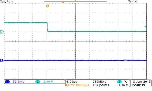
Figure 4: Output voltage when enable transitions low (32Ω)
Several factors can affect pop/click noise performance in op amps driving headphones. By including a pop/click noise-suppression circuit, the OPA1622 can improve the overall user experience in audio applications.
Do you have experience with pops and clicks in your system? Log in, leave a comment and let us know about your system design.
Additional resources
- Watch a four-part TI Precision Labs – Op Amps training course on low-distortion design.
- Search TI Designs – Precision reference designs to help get your next design started.
- Download the OPA1622 TINA-TI™ SPICE macromodel.
- Learn about TI’s entire portfolio of amplifier ICs and find technical resources.