

“Hey! Turn it down!”
You’ve probably heard these words at some point, especially if you’re like me and enjoy listening to music LOUD! If you decide to oblige and actually “turn it down” then what must you do? Reach for the volume control, of course!
What is a volume control? Put simply, it’s a circuit which attenuates the amplitude of an audio signal. Usually the desired behavior is for the amount of attenuation to vary from none, down to some high level of attenuation so that the audio is too quiet to hear. Many audio devices are digitally controlled, but there are still plenty of systems out there with a knob that you can rotate in order to adjust volume.
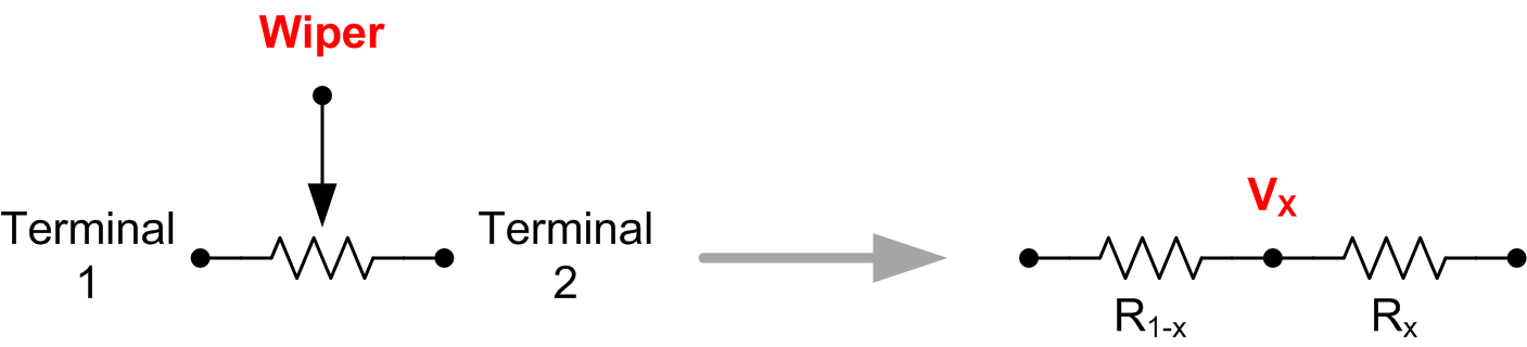
Figure 1 - The Potentiometer
This knob is actually an electronic component called a potentiometer, or pot, as shown in Figure 1. Pots are a special type of resistor with a third terminal, called a wiper. The wiper moves back and forth as you rotate the knob, changing the amount of resistance seen at the wiper terminal. This creates a voltage divider kind of behavior, making pots ideal for use in volume control circuits.
However, not all pots are created equal. The three most common types, or tapers, are the linear taper, logarithmic (or audio) taper, and reverse logarithmic (or reverse audio) taper. Figure 2 shows how the resistance of each taper changes versus rotation.

Figure 2 - Typical Potentiometer Characteristics
Human hearing spans a large dynamic range, so logarithmic units of decibels (dB) are typically used to describe the power of audio signals. An ideal volume control would have an attenuation characteristic which is linear in dB, since the result is a very natural change in volume as you rotate the volume knob. For this reason, audio taper pots are often used as volume controls. However, as you can see from Figure 2, these pots are not actually logarithmic, but rather a combination of two linear pots with different slopes. This does a poor job of achieving linear-in-dB attenuation, but thankfully there’s a better way!
 Figure 3 - Baxandall Active Volume Control
Back in 1980, Peter Baxandall presented a circuit which has become known as the Baxandall Active Volume Control, shown in Figure 3. It’s simple, flexible, and achieves excellent linear-in-dB attenuation performance with a linear pot by implementing a clever type of shunt feedback. The high input impedance and low output impedance of this circuit ensure that its attenuation performance is maintained no matter what kind of source and load impedance is connected.
 Figure 4 - Baxandall Active Volume Control Analysis
The transfer function of this circuit can easily be analyzed using Kirchoff’s current law and Ohm’s law. I won’t go through the full analysis here, but this is the result:
![]() An important note about this transfer function is that Rx represents the percentage of pot resistance after the wiper, and R1-x
An important note about this transfer function is that Rx represents the percentage of pot resistance after the wiper, and R1-x
represents the percentage of pot resistance before the wiper. If you plot this transfer function versus percentage of pot rotation, as shown in Figure 5, you can see that a nearly perfect linear-in-dB attenuation characteristic is achieved. The attenuation drops off sharply as rotation goes to zero, since the transfer function approaches negative infinity. This is actually desirable, since in a real circuit this would provide a very low “off” volume which is inaudible.
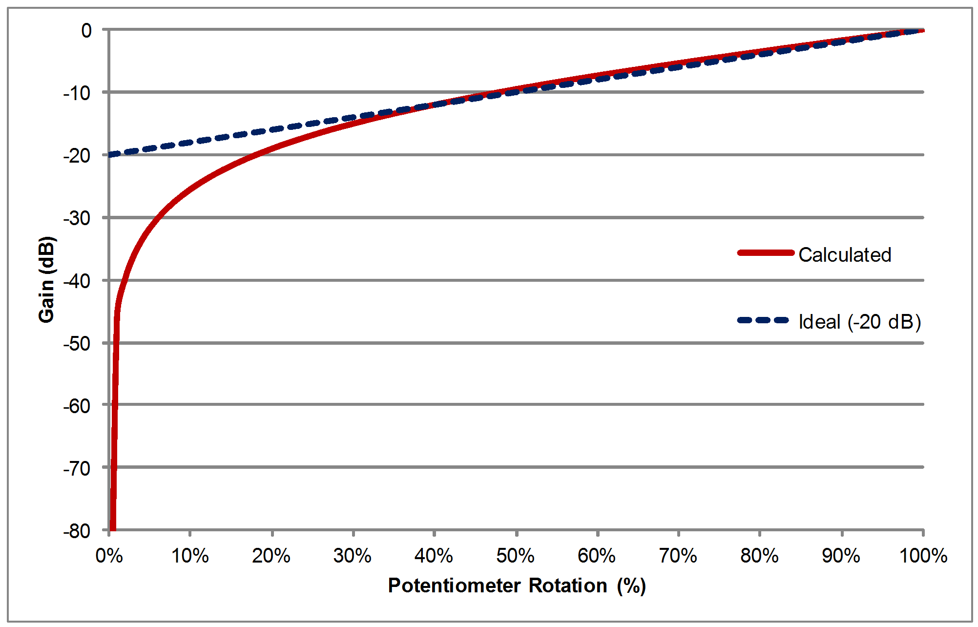
Figure 5 - Calculated Volume Control Response
The Baxandall Active Volume Control circuit is used as the basis of a TI Precision Design: Active Volume Control for Professional Audio. In this design, I provide a detailed analysis of the theory behind this circuit, as well as full simulation and real-world results and all the circuit board schematic, layout, and bill of materials files. If you have an interest in audio, I highly recommend that you check it out!
-

Wayne Bonin
-
Cancel
-
Up
0
Down
-
-
Reply
-
More
-
Cancel
Comment-

Wayne Bonin
-
Cancel
-
Up
0
Down
-
-
Reply
-
More
-
Cancel
Children