

Calculating the total error of a system can be tricky, especially when the specifications units vary widely. When calculating the total error, all specifications must be converted into a common unit before combining. This blog will show you how to convert between units of volt, percentage and parts per million (ppm) to ensure proper calculation of total system error.
Most errors in a linear device’s datasheet are referred to the input (RTI). Referring errors to the input has three main benefits: It separates each error’s contribution to the total error at the output, eliminates the need to know the gain of the device, and simplifies the calculations to refer the total error to the output. To convert input referred specifications between units of volts, percentage, parts per million, and refer the total error to the output use the following equations.
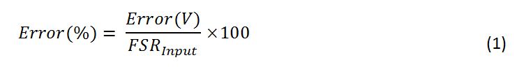
To convert from volts to percentage:
Where,
Error(V) = The error in units of volts.
Error(%) = The error as a percentage of the full-scale range.
FSRInput = The full-scale range of the input.
To convert from percentage to ppm:

Where,
Error(ppm) = The error in parts per million of the full-scale range.
To refer all errors to the output in units of volts:

Where,
Total Output Error(V) = Total error referred to the output in units of volts.
FSROuput = The full-scale range of the output.
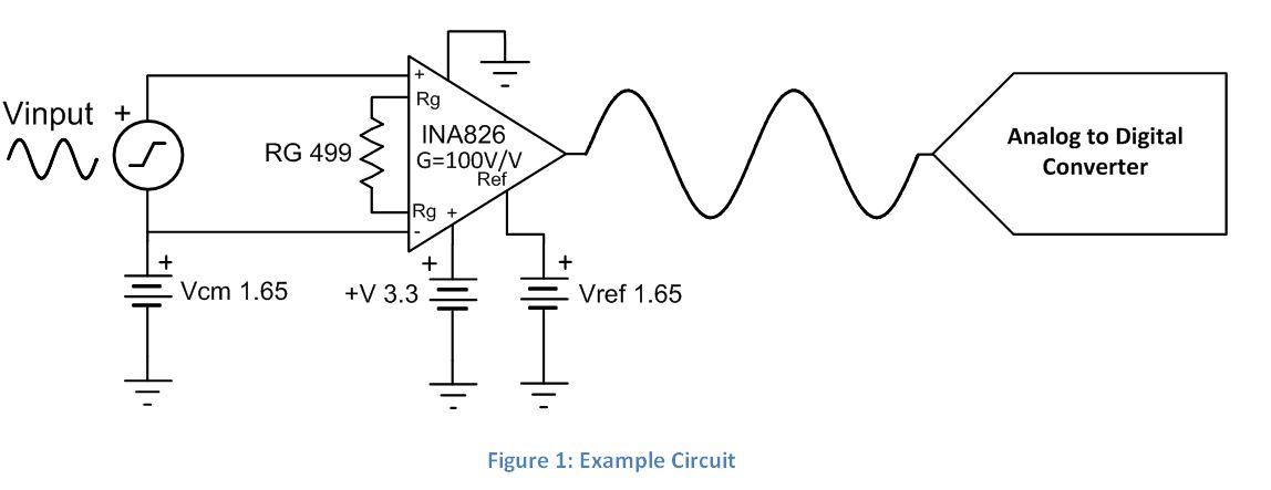
To show an example of how to use the above equations, we will use the circuit shown in Figure 1 and calculate the combined error in ppm due to a couple specifications of the INA826. The circuit has an input signal of 20mVpp, and RG is set for the INA826 to have a gain of 100V/V.
The first error we will look at is input offset voltage. Figure 2 shows the input offset voltage specification for the INA826.
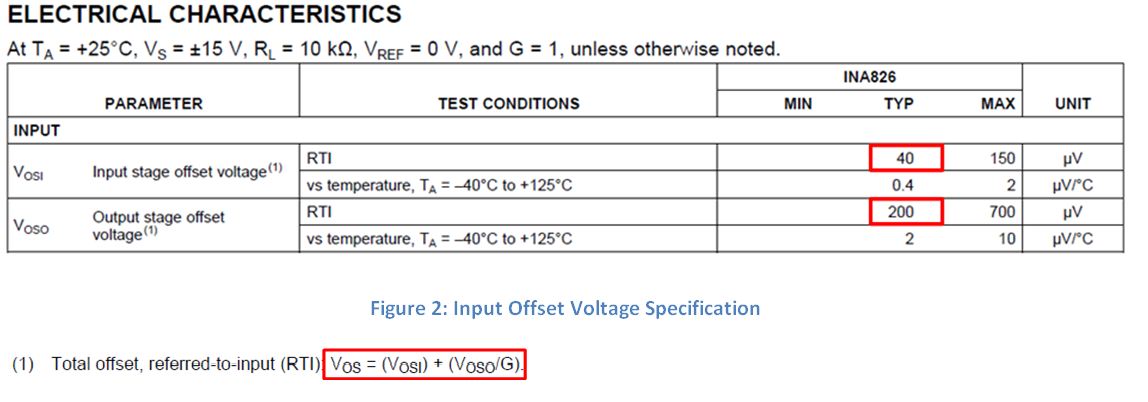
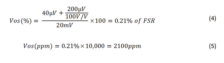
Since this specification is in units of volts, use Equations 1 and 2 to convert this to ppm. To solve Equation 1 we need to know the full-scale range of the input. The FSR of Figure 1 is the total voltage range at the input of the INA826. In this case, it is 20mVpp. Now that we have all the needed information, let’s plug in the numbers.
Now lets look at gain error. Figure 3 shows the gain error specification for the INA826.
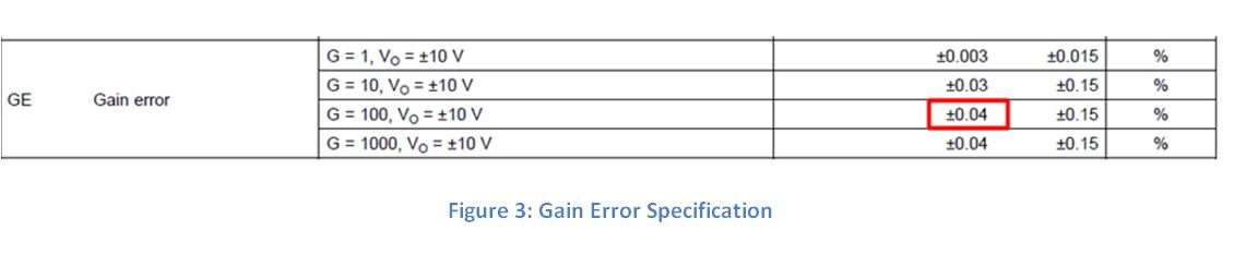
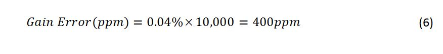
The gain error specification is given as a percentage. Therefore, we only need to use equation 2 to convert to ppm.
Now that both sources of error are in units of ppm, we can combine them by calculating the RSS, or root-sum-square, value as shown in Equation 7.

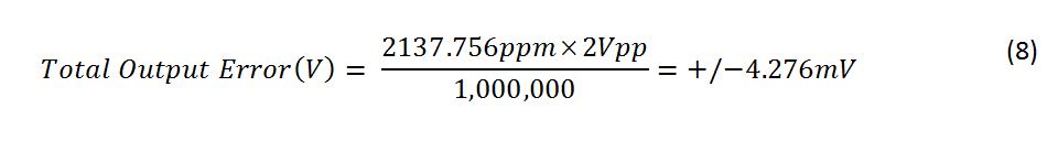
This is the total error due to the gain error and offset voltage referred to the input. However, most people want to see how much error they can expect to measure at the output. To refer the error to the output, use Equation 3. Equation 3 uses the variable FSROutput, which is the full-scale range of the output. In the example shown in Figure 1, the FSR of the output is 2Vpp. This is calculated by multiplying the input signal (20mVpp) and the gain (100V/V). The total voltage error at the output is calculated in Equation 8.
Although these are not all the errors of the INA826, a similar analysis can be done to include them.
Now that you know how to convert specifications between units of volts, percentage, and parts per million, you can now calculate the total error of your system. If you would like another example of how to calculate total system error, check out Appendix B in TI Design TIPD156.