

Last year, my colleague Tony Calabria and I brought the DAC Essentials blog series to Analog Wire. In the series, we discussed the static and dynamic specifications of precision digital-to-analog converters (DACs), precision DAC architectures, and DC error calculations.
This year on The Hub, we’re taking our writing to the next level with application-based follow ups to DAC Essentials, starting with a “mini-series” of posts focused on industrial control applications.
I’ll start that series today with a look at where DACs are used in industrial control systems. I’ll also explore the difference between two-wire and three-wire/four-wire systems.


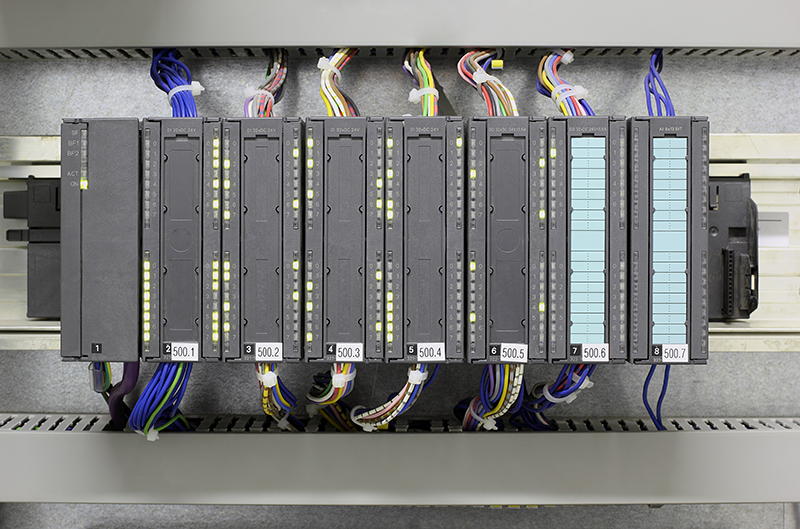
In industrial control applications, DACs are most often found in either analog outputs used for programmable logic controllers (PLCs), pictured to the left in the image above, and sensor transmitters (also called field transmitters), pictured to the right.
In both cases, the DAC may be used to deliver a voltage output or a current output. Current outputs are most common – occupying roughly 75% of the space.
Voltage outputs tend to be one of four ranges: 0-5V, 0-10V, +/-5V, and +/-10V, although there are some exceptions that require over-range outputs. Current outputs are generally referred to as one range of 4-20mA, but very often slightly wider ranges are used – sometimes as wide as 3.5-25.5mA.
While analog outputs in PLCs and sensor transmitters both use the same voltage and current output ranges, how they are used differs.
A PLC analog output usually controls some part of a system with its output, potentially spinning a motor with a voltage output or moving a linear actuator to control a valve with a current output. Analog outputs in sensor transmitters, meanwhile, are paired with a sensor and placed remotely in the field to monitor some parameter of a system.
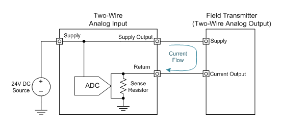
Figure 1
Figure 1 depicts typical system architecture for a PLC analog input module paired with a field transmitter in a two-wire configuration. The configuration is called a two-wire system because the analog output module only features two terminals: a supply terminal and a ground terminal. The analog input module provides the field transmitter with supply voltage/current and the two-wire field transmitter precisely controls the magnitude of its return current to the input module to establish communication. A unique challenge for the two-wire field transmitter is keeping the current consumption of all of its components under 4mA in order to communicate over the standard 4-20mA loop.
Sometimes the sensor used in the sensor transmitter requires more excitation current than the two-wire loop powered system can provide. In those cases, a three-wire approach is used for the sensor transmitter that includes independent supply terminal, current output terminal, and ground terminal. This is illustrated in Figure 2. Alternatively, sometimes a local isolated supply can be provided to the two-wire system.

Figure 2
Analog outputs in PLCs bear a strong resemblance to the three-wire configuration above. The main difference is the power supply is provided locally by a backplane, depicted by a supply terminal in the figure below. Remember that in this case, the analog output is located in the control level and it’s driving a load in the field level.
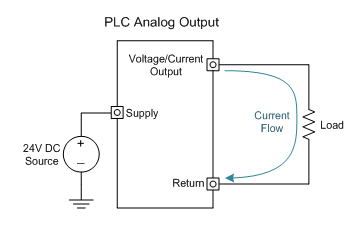
Figure 3
In the coming months I’ll provide example designs for two-wire and three-wire configurations, dig into industrial transients and transient protection circuits, and provide a few more tips and tricks for your industrial analog output designs.
Stay tuned!