

A few years ago, a customer asked me a rather surprising question: “I realize I am exceeding the maximum supply-voltage rating, but how long will your OPA373 operational amplifier continue to operate if it is powered by a 12V supply?” The operational amplifier (op amp) in question has an absolute maximum supply rating of 7V.
I told him that it would only be a matter of time before he would begin to have field failures and all of the op amps subjected to the overvoltage would eventually fail earlier than he might expect. The customer assured me that he was in the process of correcting the error and that future production would use an amplifier that could operate safely with 12V.
Applying a voltage to a circuit that exceeds the op amp supply, or any other component’s maximum rating is inviting trouble. A small overvoltage probably won’t trigger an immediate failure, but as an applied overvoltage becomes larger, the possibility for spontaneous, catastrophic failure increases dramatically. Integrated circuits (ICs) have some supply voltage guard banding to accommodate normal process variances. However, they are in place to assure that the product always operates when using supplies set within the specified power-supply range.
Figure 1 illustrates an example of an op amp power-supply range that includes a region where safe operation is assured, and unsafe regions where its lifetime may be reduced or cut very short. The op amp in this case is a classified as a low voltage op amp, fabricated on a complementary metal oxide silicon (CMOS) semiconductor process. The amplifier’s supply increases on the vertical scale from 0V to a level beyond its absolute maximum voltage, where catastrophic failure is inevitable.
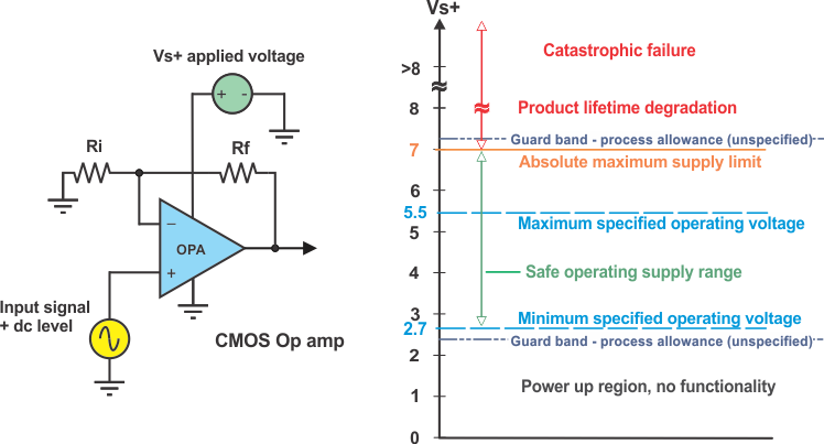
Figure 1: CMOS op amp power supply regions
Instantaneous failure can happen when the insulating dielectric materials separating the IC elements cannot withstand the potential difference applied between them. Circuit points where V+ and V- (GND) are physically very close might exhibit the highest electrical field intensity and potential for breakdown. There may be other circuits where the voltage difference is less, but because of very high field intensity, breakdown might occur first. Should that happen, high current flows through the minute metal traces and/or silicon, resulting in very high localized current and power densities, and near instantaneous super-heating in the immediate area. The associated metal and/or silicon melt and are redistributed on and within the IC structure. They solidify quickly, creating unintended conductive short circuits and/or open circuits. In addition, damage to semiconductor junctions can occur if the current flow through junctions is excessive. The IC is damaged and rendered useless and may now draw excessive current.
So what about the customer case where the amplifiers continued to function despite having the V+ maximum rating exceeded by a full 5V? Immediate breakdown did not occur and they continued to function in the field. Even so, the customer should not expect the devices to operate correctly long-term and they may eventually incur catastrophic failure. Delayed failure of an IC can take moments, months or even years to happen.
Although an applied voltage may not be high enough to trigger instantaneous failure, it may be high enough to move the transistor operating conditions from safe and normal to unsafe and abnormal. The higher voltage conditions and increased field intensities can negatively affect the precisely constructed semiconductor structures and junctions resulting in excessive operating current levels, unintended current paths (latches), increased leakage currents and increased self-heating. The amplifier circuit may still function, but it may not operate with the same electrical performance.
For example, CMOS op amps may enter an unintended bias condition called hot carrier injection. It occurs when excessively high voltage is applied between the drain and sources of the MOS field effect transistors (MOSFETs). Accelerated electrons are injected into the transistor’s gate oxide causing a shift in its threshold voltage. The shifts continue with continued exposure to the high electric field conditions. The MOSFET electrical characteristics become affected over time and in turn, the overall performance of the op amp may degrade. Always avoid exposing any op amp, CMOS, bipolar or junction FET (JFET) even for a moment to a moderate-to-high overvoltage supply level.
When operated within the specified supply range, an amplifier IC can operate continuously and reliably, often for many decades. Just how long its lifetime might be is predictable by applying the Arrhenius equation. My colleague Marek Lis covered this subject at length in another Precision Hub blog post. However, for overvoltage conditions, things are not as straightforward, and it is nearly impossible to determine how long the amplifier will last.
As odd as it might seem, I have encountered instances where customers had powered their amplifier circuit with too low of a supply voltage, yet they observed mostly normal operation from the circuit. This supply condition falls somewhere in the power-up region of Figure 1. In my next post, I’ll examine amplifier operation at this other end of the supply-voltage range.
Additional resources:
- Learn about TI’s precision operational amplifier portfolio.
- Find useful analog design formulas in the Analog Engineer’s Pocket Reference.
- Watch on-demand training courses on stability and more in TI Precision Labs – Op Amps.
