

This is the second post a three-part blog series on electrical overstress (EOS) from amplifier expert Art Kay. Get more tips on how to avoid damage from EOS from the first and third installments of Art's series.
In the last electrical overstress blog we introduced the absolute maximum specification table and described how a series resistor can be used to protect the inputs from electrical overstress. Exceeding the power supply voltage is another common overstress issue. One possibility is that a large transient voltage is coupled into the power supply. This can happen from inductive kickback of a load such as a motor start up. Large transient voltage on the supply is a common problem in many real world systems, and you should always design to protect your application from this problem.
The most common way to protect against power supply transients is to have a transient voltage suppressor (TVS) on each supply. The TVS will limit the supply voltage to a safe level so that the maximum supply voltage is not exceeded. We introduced the TVS in the previous blog. In this blog we will continue the discussion by explaining the TVS specifications.
Figure 1 illustrates the typical V-I characteristics for a TVS device. As was mentioned previously, the device behaves much like a zener diode except that it is optimized to react quickly to large transient currents. Also, the specifications of a TVS highlight key characteristics that are important to protection against transient overvoltage. Table 1 gives an example TVS specification. Notice that all the specifications correspond to key points on the V-I curve. As we describe the specifications refer to the V-I curve to help clarify the meaning of the specification.
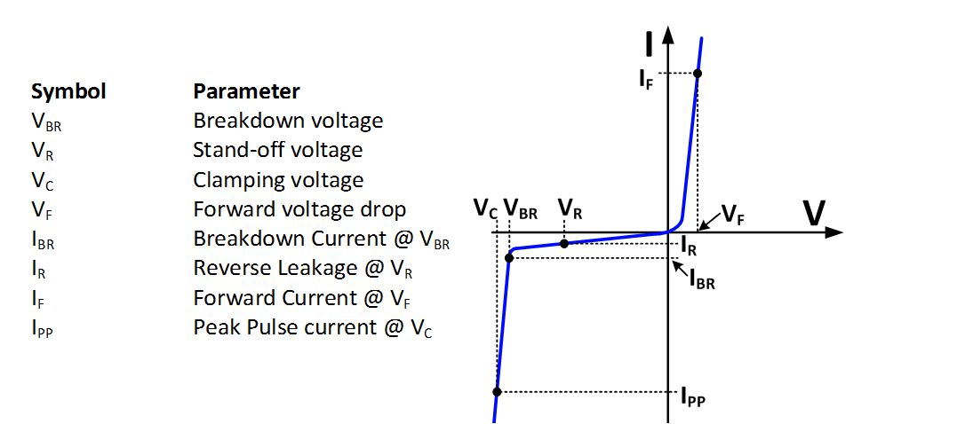
Figure 1: V-I Characteristics for a TVS
Table 1: Example specifications for a Transient Voltage Suppressor
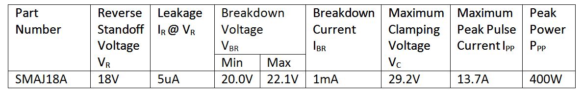
The reverse standoff voltage (VR) is the normal operating voltage for the TVS device. At this voltage level, the device is effectively “off” and will have a specified leakage current. The leakage current (IR) is normally in the micro-amp level. This current adds to the total power supply current and can be a concern for low power applications. Increasing the supply beyond the reverse standoff voltage will cause leakage to increase, and the TVS will eventually breakdown when the breakdown voltage (VBR) is reached. Figure 1 shows where VR is on the TVS V-I curve. From Table 1 you can see that VR = 18V, and IR = 5µA in the example TVS specification.
The breakdown voltage (VBR) is the point at which TVS protection begins to breakdown or “turn on” and starts to draw significant current. After it breaks down, the voltage across the TVS will “clamp” to a relatively constant voltage. From Table 1 you can see that VBR ranges from 20V to 22.1V, with a 1mA breakdown current (IBR) for our example TVS specification.
Referring to figure 1, notice that although the voltage is relatively constant after breakdown, there will be some voltage increase with increasing current. The clamp voltage (VC) is defined to help understand how voltage increases across the TVS after breakdown. The clamp voltage is the voltage drop across the TVS when it is on and drawing significant current. For some devices a few different clamp voltages are given at different current levels. In this example, the TVS maximum clamp voltage is given as VC = 29.2V at a current of IPP = 13.7A. In the next blog we will learn how to estimate the clamp voltage for different current levels.
In this blog, we discussed the key specifications for TVS devices. In the next blog we will show how to select a TVS device that will protect your application.
If you found this of interest, be sure to check out the other posts in my "Electrical overstress in a nut shell" series.
References:
1. Walters, Kent. “How To Select Transient Voltage Suppressors”, MicroNote 125, July 1999. www.microsemi.com
2. STMicroelectronics, “ESDA-1K Data Sheet”, Doc ID 17883 Rev 1, September 2010, V-I curve, Page 2. http://www.st.com/web/en/press/c2747