

This is the final post a three-part blog series on electrical overstress (EOS) from amplifier expert Art Kay. Get more tips on how to avoid damage from EOS in the first and second installments of Art's series.
In the last electrical overstress blog we introduced the specifications for a Transient Voltage Suppressor (TVS). In this blog we will go through a step by step procedure for selecting the best TVS for your design.
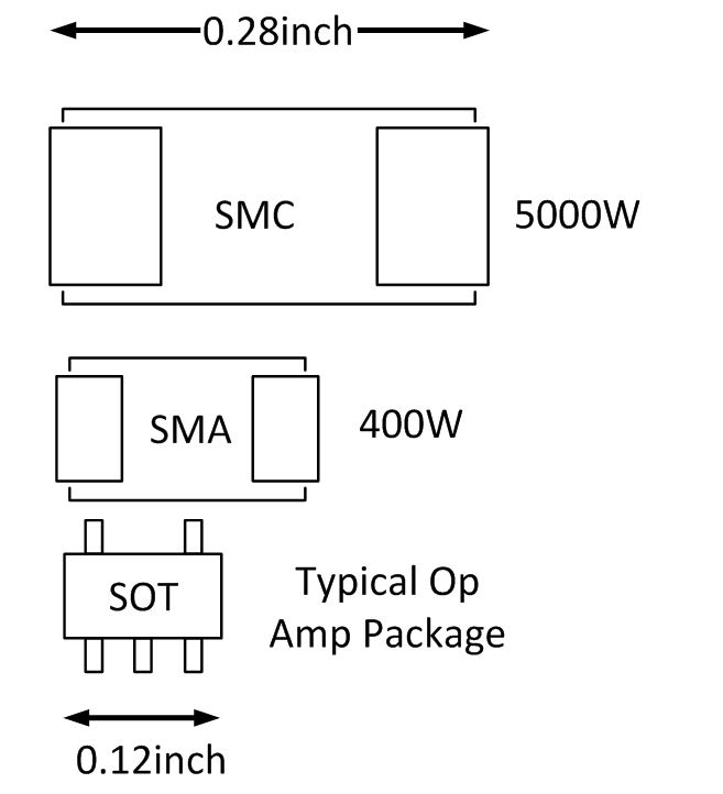
1. Consider the package size and maximum power dissipation. The power rating for a TVS is generally calculated as the maximum clamping voltage multiplied by the maximum peak pulse current (PPP = IPP∙VC). The maximum power dissipation is for typically for a 1ms pulse. One advantage to using a TVS with a high power rating is that the slope of the V-I curve in the (breakdown) region is very steep. We will discuss the V-I characteristic in the clamp region in more detail later, but the important point is that the voltage regulation during a fault condition is better for the device with the higher power rating for a given fault current.
Notice in Figure 1 that the power dissipation is related to package size. Unfortunately, the package size of a TVS can be large compared to the amplifier package. However, if may not be necessary to have a TVS for each amplifier. One TVS may be used for the entire supply bus, or perhaps a few could be used for a large PCB. In this example, we will choose the 400W package to minimize the TVS size. In later calculations will see how the fault voltage increases for large fault currents.
Figure 1: Example package size and power dissipation for TVS
2. Choose the reverse standoff voltage to be equal to the maximum normal operating supply voltage for your application. In this example, the largest supply voltage is equal to the specified maximum (±18V from Table 3), so we will select the standoff voltage to be 18V. As long as the supply is less than the reverse standoff voltage, the TVS leakage current will remain relatively low (typically micro-amps) and is generally specified by over the full temperature range in the TVS data sheet. Table 1 shows some examples of a TVS with an 18V standoff voltage and their associated 5uA and 10uA leakage currents.
Table 1: Example specifications for a Transient Voltage Suppressor (400W and 5000W options)
|
Part Number |
Reverse Standoff Voltage VR |
Leakage IR @ VR |
Breakdown Voltage VBR |
Breakdown Current IBR |
Maximum Clamping Voltage VC |
Maximum Peak Pulse Current IPP |
Peak Power PPP |
|
|
Min |
Max |
|||||||
|
SMAJ18A |
18V |
5uA |
20.0V |
22.1V |
1mA |
29.2V |
13.7A |
400W |
|
5.0SMDJ18A |
18V |
10uA |
20.0V |
22.1V |
1mA |
29.2V |
172A |
5000W |
Table 2: Absolute Maximum Ratings Table for OPA192
|
|
VALUE |
UNIT |
||
|
Supply voltage |
±20 (+40, single supply) |
V |
||
|
Signal input terminals |
Voltage |
Common-mode |
(V-) - 0.5 to (V+) + 0.5 |
V |
|
Differential |
(V+) - (V-) + 0.2 |
V |
||
|
Current |
|
±10 |
mA |
|
|
Output short circuit |
Continuous |
|
||
|
Operating temperature |
-55 to +150 |
℃ |
||
|
Storage temperature |
-55 to +150 |
℃ |
||
|
Junction temperature |
+150 |
℃ |
||
|
Electrostatic discharge (ESD) ratings |
Human Body Model (HBM) |
4 |
kV |
|
|
Charged device model (CDM) |
1 |
kV |
||
Table 3: Operating Specifications for OPA192
ELECTRICAL CHARACTERISTICS
At TA = +25C, VCM = VOUT = VS/2, and RLOAD = 10kΩ connected to Vs/2, unless otherwise noted.
|
PARAMETER |
TEST CONDITIONS |
MIN |
TYP |
MAX |
UNIT |
|
|
POWER SUPPLY |
||||||
|
VS |
Specified voltage range |
|
+4.5 |
|
+36 |
V |
|
IQ |
Quiescent current per amplifier |
IO = 0A |
|
1 |
1.2 |
mA |
|
TA = -40C to 125C, IO = 0A |
|
|
1.5 |
mA |
||
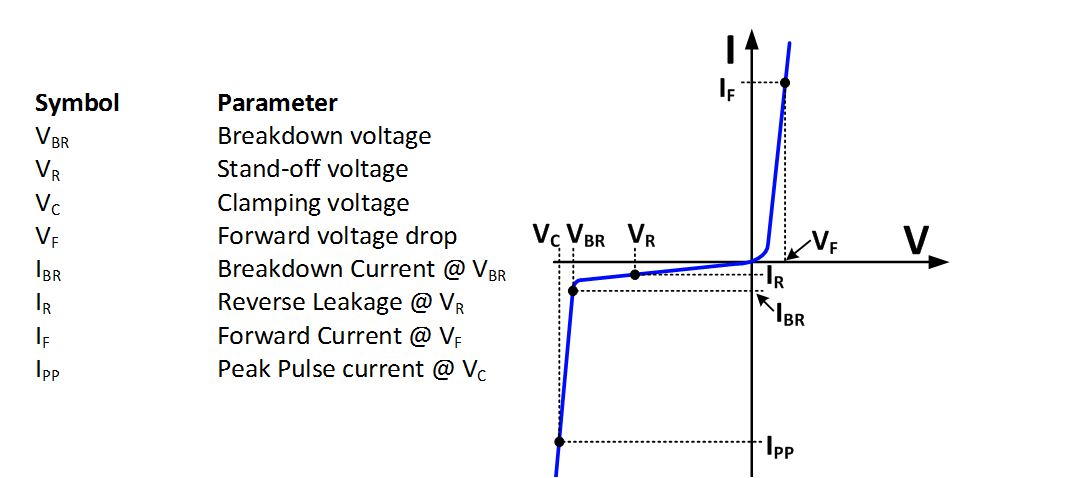
3. Determine the relationship between voltage and current when the TVS device is turned on and protecting the amplifier. To understand this relationship, you will need to consider the breakdown voltage (VBR) and the clamp voltage (VC). The breakdown voltage (VBR) is the point at which TVS protection begins to breakdown or “turn on” and starts to draw significant current. Increasing current through the TVS will cause the voltage across it to increase somewhat. This increase happens from series resistance and self heating of the device. The clamp voltage is the voltage across the TVS for a specified large current. In the example, the clamp voltage is 29.2V for a 13.7A current (see Table 1, 400W option). The goal of the TVS is to limit the voltage to less than the amplifiers absolute maximum rating. The actual voltage across the TVS will depend on the current through it, and the voltage will be between the breakdown voltage and the clamp voltage.
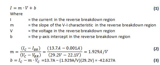
Referring to Figure 2, you can see that the V-I characteristic between the breakdown voltage and clamp voltage is linear. It is possible to use these two points to derive an equation for the line. This equation can be used to determine the reverse voltage for any current between the breakdown current and the maximum peak pulse current. This equation will tell us the maximum voltage that our application will see based on the expected fault current. Equations (1) to (3) show the linear equation as well as the derivation of the slope and intercept for this example.
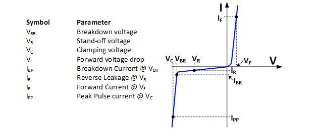
Figure 2: V-I Curve for a TVS Device
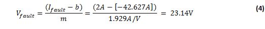
4. Estimate the worst case current that will flow in the TVS during a fault, and calculate the corresponding fault voltage. The ultimate goal is to limit any over voltage conditions to a safe level (i.e. below the absolute maximum supply voltage). In order to estimate the fault voltage we really need to know what fault current we can expect. The expected fault current depends on the application. If the supply is connected to an inductive load, or the application is in the presence of strong electromagnetic fields the fault current may be high. If the supply is well behaved and the application is in a shielded environment the fault current may be low. Making this estimate may involve some engineering assumptions, and will depend on how conservative you want to be. For our example problem I will choose a fault current if 2A. Using the linear equation, the fault voltage is limited to 23.14V, see Equation (4).
5. Compare the fault voltage to the amplifiers absolute maximum voltage. The absolute maximum voltage is ±20V for this example, see Table 2. The maximum fault voltage in this example is 23.14V for a 2A fault, see Equation (4). Ideally the fault voltage should be less than or equal to the absolute maximum to prevent damage to the device. This TVS does not meet this requirement. Below are three options to consider if the fault voltage is greater than the absolute maximum voltage.
a. Use a lower nominal operating supply voltage. In this example, we set the nominal supply voltage to ±18V, so the standoff voltage (VR) was also set to 18V. The absolute maximum for this device ±20V. There is only a 2V difference between the operating voltage and the absolute maximum voltage. If you intentionally use a lower nominal supply voltage (e.g. ±15V) , the margin between nominal supply and absolute maximum is larger (e.g. Vmax – Vnominal = 20V – 15V = 5V). This wider margin makes it easier to find a TVS that meets the requirements.
b. Look for a better TVS. Some TVS diodes may be better suited to your application than others. In this example, we selected a TVS with a 400W rating. Choosing a device with a higher power rating would reduce the fault voltage at 2A. In this example, using a 5000W rather than a 400W TVS would reduce the fault voltage from 23.14V to 22.59V. Nevertheless, you will never find a device with ideal characteristics, because there are limits to the manufacturing process.
c. Use the TVS even though the fault voltage is greater than the absolute maximum supply voltage. On the surface, it sounds like a really bad idea to allow for fault voltages that exceed the absolute maximum specification. However, some protection is always better than no protection. In many cases it is not practical to find a TVS that is off over the operating voltage range but turns on just before the absolute maximum supply limit. One thing to keep in mind is that there is some margin in the absolute maximum specification.
6. Consider the cost. Once you have narrowed down your search, cost can be used to make the final selection.
If you found this of interest, be sure to check out the other posts in my "Electrical overstress in a nut shell" series.
References:
- Walters, Kent. “How To Select Transient Voltage Suppressors”, MicroNote 125, July 1999. http://www.ti.com/hpa-pa-opamp-thehub-20140711-part3-externalpage1-en
- STMicroelectronics, “ESDA-1K Data Sheet”, Doc ID 17883 Rev 1, September 2010, V-I curve, Page 2. http://www.st.com/web/en/press/c2747