

Welcome to part three of this blog series discussing electromagnetic compatibility (EMC) testing. In parts one and two we discussed the background of certification testing and the specifications for ESD and radiated EMI immunity tests. This time, we’ll continue with the details of electrical fast transient (EFT) and surge testing.
IEC 61000-4-4: EFT (Electrical Fast Transients)
EFT events occur as a result of arcing contacts in switches and relays. Industrial environments leveraging electromechanical switches to connect and disconnect inductive loads may experience these issues frequently. IEC 61000-4-4 specifies the EFT threat in both power and data lines.
Table 1: IEC 61000-4-4 threat levels and test voltages
|
|
Power Supply Port |
I/O, Signal, Data and Control Lines |
||
|
Threat Level |
Open-Circuit Voltage (kV) |
Short-Circuit Current (A) |
Open-Circuit Voltage (kV) |
Short-Circuit Current (A) |
|
1 |
0.5 |
10 |
0.25 |
5 |
|
2 |
1 |
20 |
0.5 |
10 |
|
3 |
2 |
40 |
1 |
20 |
|
4 |
4 |
80 |
2 |
40 |
The EFT waveform is described in terms of a voltage across a 50 Ω load from a generator having a nominal dynamic source impedance of 50 Ω. The output occurs as a burst of high voltage spikes at a repetition rate ranging from 2 kHz to 5 kHz. The burst length is defined as 15 ms with bursts repeated every 300 ms. Each individual burst pulse has a rise time of 5 ns and a total duration of 50 ns.
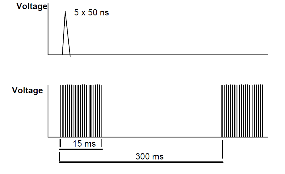
Figure 1: IEC 61000-4-4 EFT voltage waveform
During the EFT test, the engineer connects the device under test to a power supply with 3 m of cable and places it on a small wooden platform. Part of the cable passes through a special trough with wooden side panels and a triangular metallic inner chamber. The EFT generator is connected to the metallic chamber of the trough and the test waveform is applied. The EFT waveform can then couple to the device under test’s power supply cable.
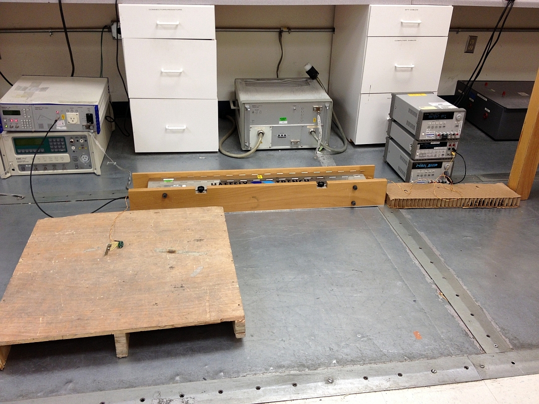
Figure 2: IEC 61000-4-4 EFT test hardware setup
IEC 61000-4-5: Surge
Lightning strikes and switching cause the most severe transient conditions on power and data lines. Switching transients include power system switching, load changesand short circuit faults. Lightning transients may result from a direct strike or induced voltages and currents due to an indirect strike.
The IEC 61000-4-5 standard defines a transient entry point and a set of installation conditions. The transient is defined in terms of a generator producing a given waveform and having a specified open circuit voltage and source impedance. Two surge waveforms are specified: the 1.2 x 50 µs open-circuit voltage waveform and the 8 x 20 µs short-circuit current waveform.
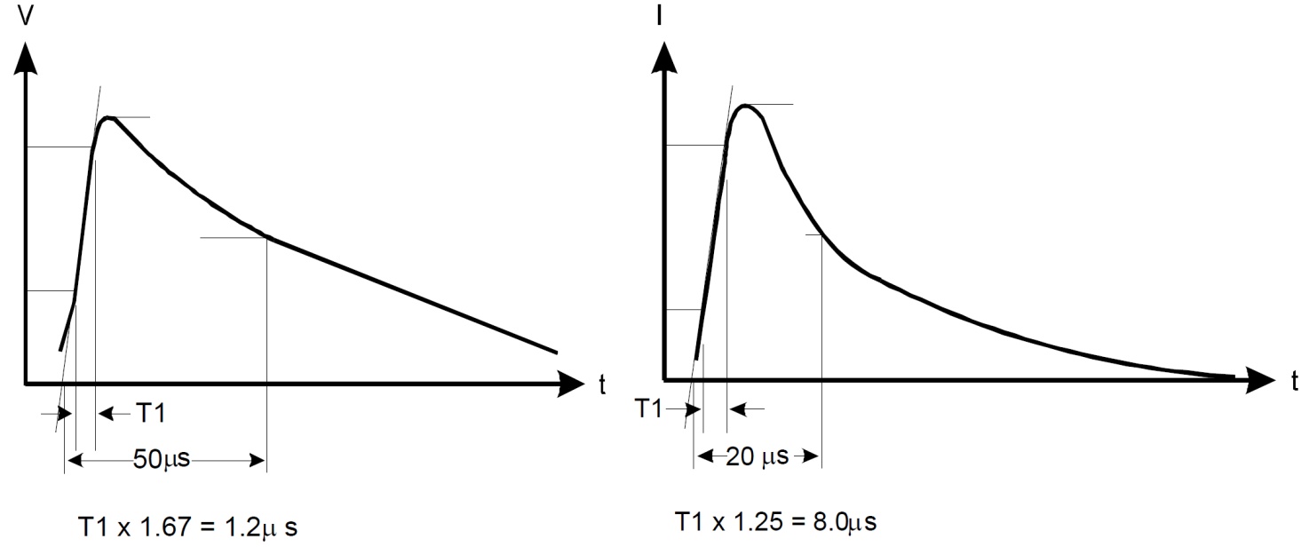
Figure 3: IEC 61000-4-5 surge waveforms
Table 2: IEC 61000-4-5 threat levels and test voltages
|
Threat Level |
|
Power Supply |
Unsym Lines (Long Distance Bus) |
Sym Lines |
Data Bus (Short Distance) |
||
|
Coupling Mode |
Coupling Mode |
Coupling Mode |
Coupling Mode |
||||
|
Line-Line ZS = 2Ω |
Line-GND ZS = 12Ω |
Line-Line ZS = 42Ω |
Line-GND ZS = 42Ω |
Line-GND ZS = 42Ω |
Line-GND ZS = 42Ω |
||
|
1 |
Voltage |
n/a |
0.5 kV |
n/a |
0.5 kV |
1 kV |
n/a |
|
Current |
n/a |
42 A |
n/a |
12 A |
24 A |
n/a |
|
|
2 |
Voltage |
0.5 kV |
1 kV |
0.5 kV |
1 kV |
1 kV |
0.5 kV |
|
Current |
250 A |
83 A |
12 A |
24 A |
24 A |
12 A |
|
|
3 |
Voltage |
1 kV |
2 kV |
1 kV |
2 kV |
2 kV |
n/a |
|
Current |
500 A |
167 A |
24 A |
48 A |
48 A |
n/a |
|
|
4 |
Voltage |
2 kV |
4 kV |
2 kV |
4 kV |
n/a |
n/a |
|
Current |
1 kA |
333 A |
48 A |
95 A |
n/a |
n/a |
|
|
5 |
Voltage |
Varies |
Varies |
2 kV |
4 kV |
4 kV |
n/a |
|
Current |
Varies |
Varies |
48 A |
95 A |
95 A |
n/a |
|
|
Waveforms |
Voltage |
1.2 x 50 µs |
1.2 x 50 µs |
1.2 x 50 µs |
1.2 x 50 µs |
1.2 x 50 µs |
1.2 x 50 µs |
|
Current |
8 x 20 µs |
8 x 20 µs |
8 x 20 µs |
8 x 20 µs |
8 x 20 µs |
8 x 20 µs |
|
For the surge test, the engineer places the device under test on a small wooden platform and connects to its power supply through a heavy-duty LC filter network. The surge generator is connected to the capacitors of the LC filter, allowing the device under test to be exposed to surge conditions while protecting the power supply.
The surge voltage is tested at both positive and negative polarities. Connections are made using all possible combinations across the device under test’s power supply terminals, both differentially and common-mode.
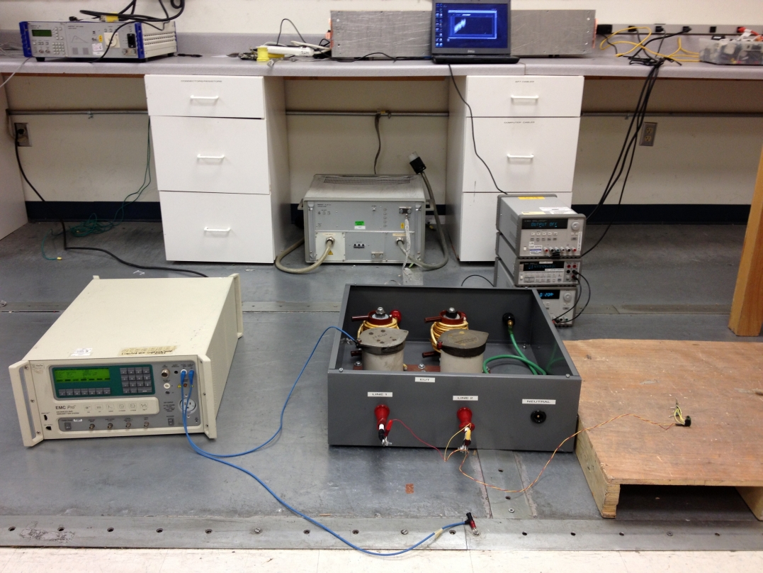
Figure 4: IEC 61000-4-5 surge test hardware setup
Stay tuned for the final installment in the series, where we’ll finish discussing the most common tests and recap what we’ve learned.
Related resources:
Bridge Sensor Signal Conditioner with Current Loop Output, EMC Protection reference design
Two-Channel Source/Sink Combined Voltage & Current Output, Isolated, EMC/EMI Tested reference design
Part I – Get CerTIfied, not certi-FRIED! Electromagnetic compatibility testing explained.
Part II – Get CerTIfied, not certi-FRIED! Electromagnetic compatibility testing explained.
-

Elcids Honorato das Chagas
-
Cancel
-
Up
0
Down
-
-
Reply
-
More
-
Cancel
Comment-

Elcids Honorato das Chagas
-
Cancel
-
Up
0
Down
-
-
Reply
-
More
-
Cancel
Children